
0. Overview
This is a design summary for a mechanical engineering senior design project aimed at creating a compact, low-voltage induction machine building kit for future use in electrical engineering courses at UW-Madison. This kit was requested by the Grainger Teaching Studio to be designed and prototyped for a new, hands-on power conversion course being offered at the university. The design summary will go through the progression and the several iterations the team created for this project.
Team Memeber: Anson Chan (Me), Jon Keller, Steven Gerbers, Nathan Seibold
1. Background
As highlighted in the earlier overview section, the core objective of this project was to develop an induction motor building kit for an upcoming electrical engineering course. This course aims to challenge students in optimizing various machine parameters, encompassing factors such as pole count, winding turns, and targeted torque. Our intention is to supply the Grainger Teaching Studio with a budget-friendly prototype that would be served as a base model that student could improve/modified upon.
Ultimately, the kit we designed would not only enrich the educational experience of students in this advanced course but also equip them with a hands-on experience in building motor as they transition into the industry.
2. What is an induction machine?
Induction machines, also known as asynchronous machines, are one of the most widely used electrical motors in both domestic and industrial applications. About 50 percent of global power is consumed by electric machines, and over 90 percent of industrial machines are induction motors [2]. One of the main reasons it is so widely used is due to its high efficiency, which can achieve as high as 97 percent [3]. The high efficiency combined with low maintenance and self- starting properties makes the induction machine one of the most popular choices within the industry.
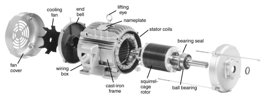
An induction machine comprises of two main components, the stationary stator and a rotating rotor. An exploded view of a common industrial squirrel cage type induction machine is shown in figure below. The main frame, typically made from cast iron, is used to house and protect the stator and rotor from damage as well as protect the user while operating. While sometimes not necessary, fans are added to the machine to prevent the stator coils from overheating.
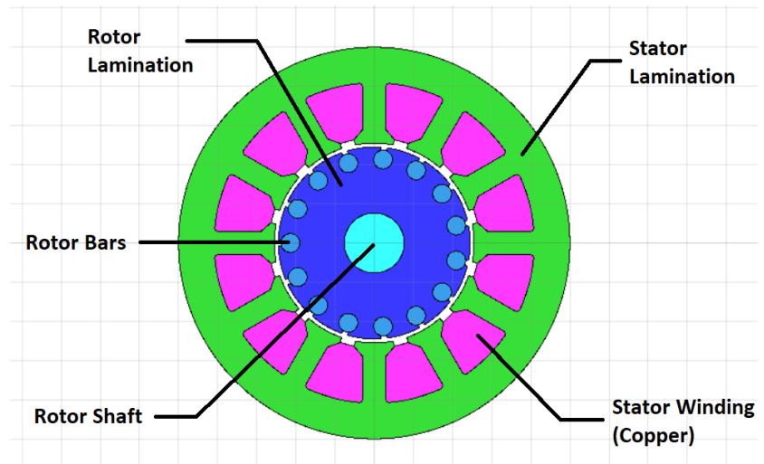
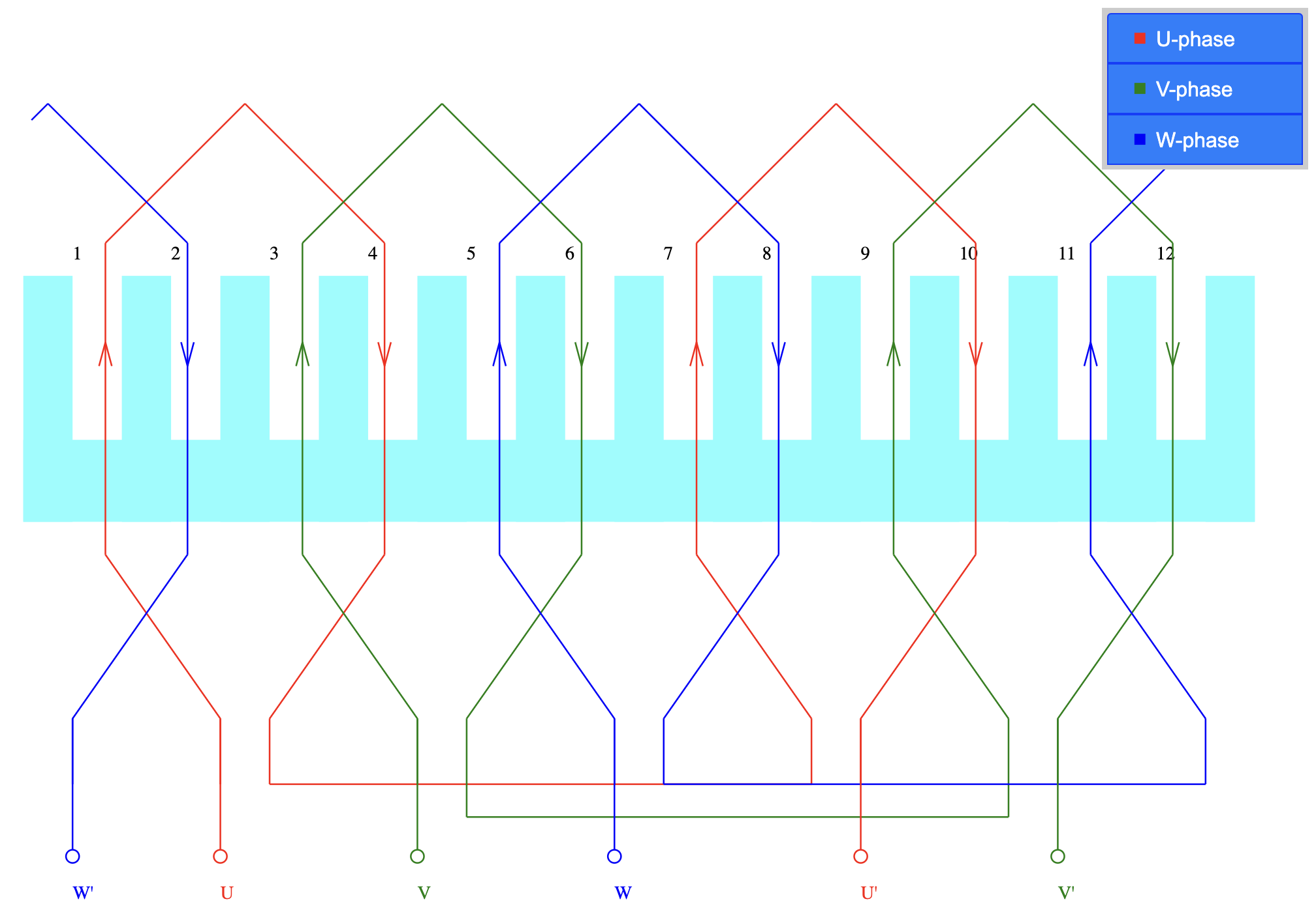
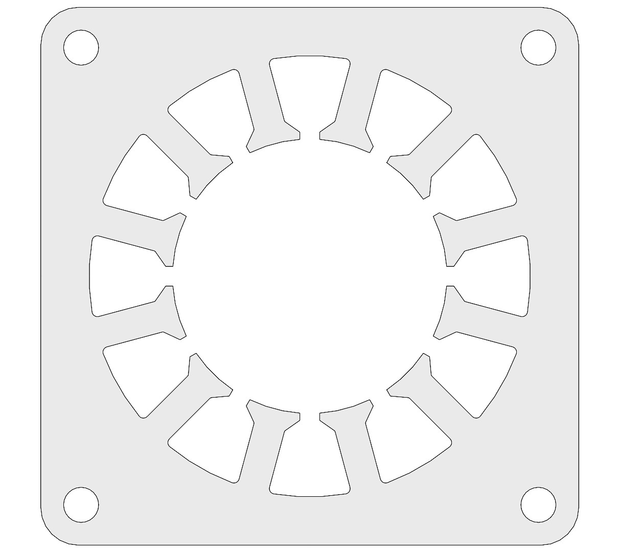
A cross-sectional view of the stator is shown below and is derived from a design software. The stator of an induction machine is typically composed of stator windings and iron laminations. The copper windings in the stator of an AC machines are typically wound in a distributed fashion, meaning they are typically spread throughout the stator lamination [4]. Since an induction machine typically has three phases, the windings would have three individual input terminals. When the three-phase windings in the stator are connected to a three-phase power source, a rotating magnetic field is generated as the electromagnets interact. This rotating magnetic field induces a current in the rotor and generates torque in the rotor, creating a rotating motion.
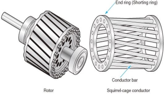
The squirrel cage rotor design uses conducting bars (typically made from copper and/or aluminum) connected to a shorting ring on either end [4]. Within the cage, iron laminations are added to assist the flow of magnetic flux generated by the stator windings. A current is induced in the rotor bars when a rotating magnetic field is generated by the stator windings. The interactions between the induced current in the rotor and the rotating magnetic field in the stator allows the generation of torque in the squirrel cage rotor, causing a rotational motion. As seen above, the bars are skewed at an angle. This is to prevent cogging, which is a locking of the rotor upon startup that commonly occurs when there is an equal number of conductor bars and stator teeth. Despite eliminating this, the motor may experience cogging in the form of running rough. The skew can help mitigate these adverse effects if properly implemented. For the scope of this project, skewing is ranked as a “nice to have” feature in later iterations but will not be included in the initial prototype.
3. Brainstorming
Since the kit we were designing was intended for students who will be participating in a semester-long electrical engineering course, the client has placed a strong emphasis on prioritizing manufacturability over performance. This is due to the limited time the students will have during the semester to assemble the kit. Additionally, the budget for each motor kit is firmly capped at $100. Together, these factors highlight the significance of manufacturability and cost-effectiveness in this project.
Beyond the considerations of manufacturability and cost, a set of constraints were also provided to us for the prototype we would be building. The constraints were,
- The maximum stator cross-sectional dimension must be 100 mm x 100 mm only, this is so the stator would fit within the existing housing design provided by the client.
- The current rating of the prototype should be capped at 5Arms or lower.
- The copper slot fill factor of the prototype should be around 40%
In addition to the specific asks from the client, for the prototype we also had to consider target values.
-
Rated Power P
- The team believes that since the main focus of the project is on manufacturability rather than optimizing the machine’s performance, the rated power becomes a less critical factor in shaping the machine’s design. As a result, we settled on a low target rated power output of around 100W for our prototype.
-
Number of poles p
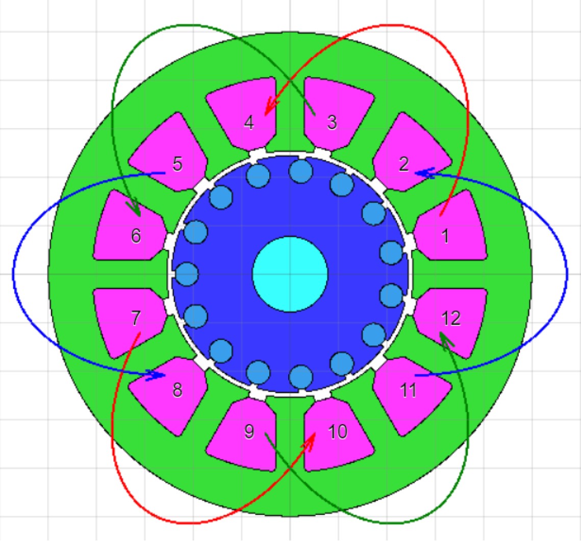
- Once more, this is closely related to the prototype’s manufacturability focus. The number of poles p, corresponds to the number of coil groups per phase. Therefore, in the case of a 3-phase machine with 12 stator slots, this would signify a 4-pole machine. Ideally, for ease of manufacturing the prototype, a 2-pole design might be considered, as that would only have 6 stator slots. However, opting for a 2-pole design also means a thicker stator back iron is needed to prevent magnetic saturation, which in turn poses challenges in an already constrained form-factor. Given these considerations, the team ultimately decided to adopt a 4-pole design. It’s noteworthy that the industry standard for induction machines also commonly favors 4-pole designs.
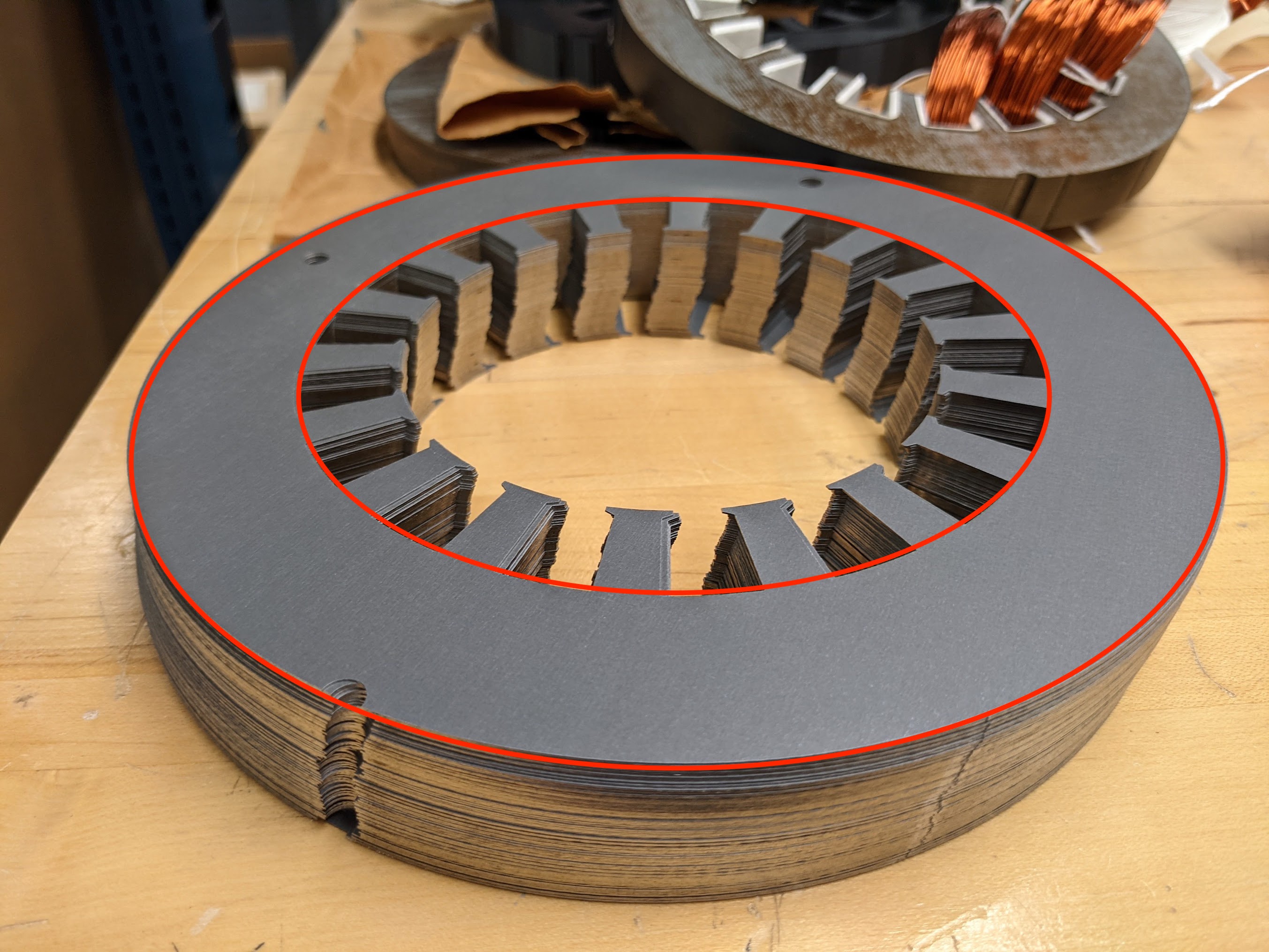
As an example, the back iron region of a stator core is between the red circles shown in the image - Once more, this is closely related to the prototype’s manufacturability focus. The number of poles p, corresponds to the number of coil groups per phase. Therefore, in the case of a 3-phase machine with 12 stator slots, this would signify a 4-pole machine. Ideally, for ease of manufacturing the prototype, a 2-pole design might be considered, as that would only have 6 stator slots. However, opting for a 2-pole design also means a thicker stator back iron is needed to prevent magnetic saturation, which in turn poses challenges in an already constrained form-factor. Given these considerations, the team ultimately decided to adopt a 4-pole design. It’s noteworthy that the industry standard for induction machines also commonly favors 4-pole designs.
-
Operating electrical frequency ω (directly affects mechanical speed)
- Client informed us that the 3-phase motor drive in the Grainger Design Lab has a range of electrical frequencies of between 50Hz and 60Hz only. Meaning, if we decided on a 4-pole design, with a 60Hz electrical frequency we would be able to achieve 1800 RPM no-load speed.
-
Single or Double-Layer winding
- For simplicity, the team chose to implement a single-layer winding. Nevertheless, the client has expressed an interest in exploring a double-layer design if time allows.
4. Design
4.1 Housing
The client supplied the housing design and specifically requested the team to incorporate into our induction machine prototype design. Animation below shows the design of the housing endplate.
4.2 Stator and Rotor
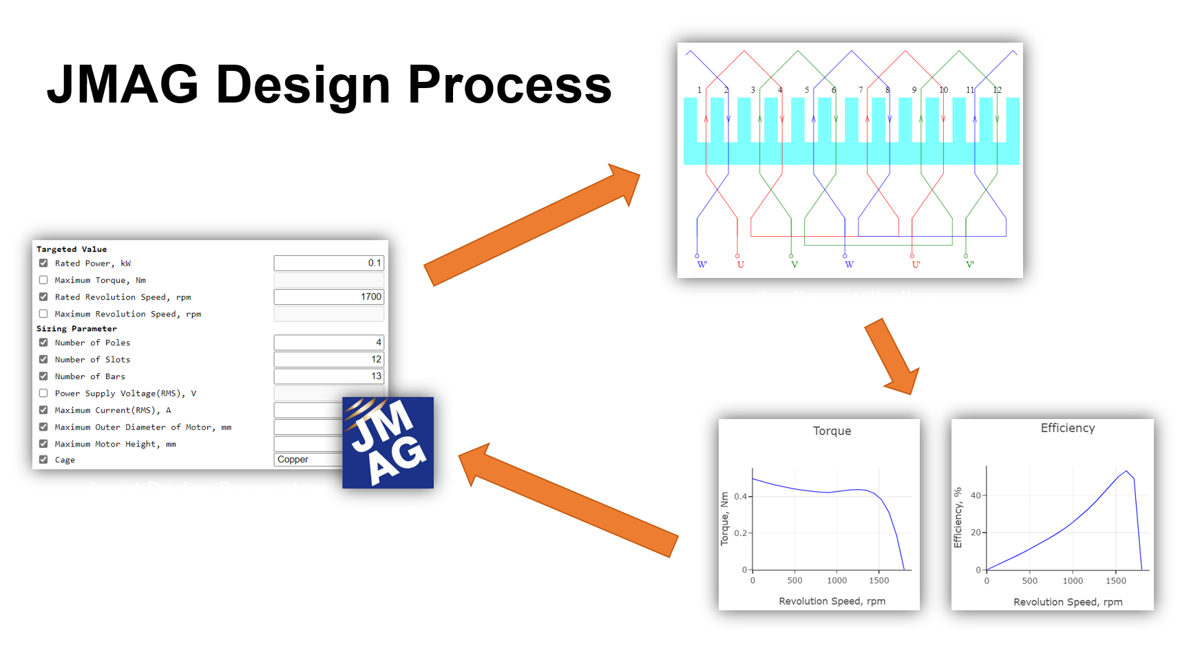
As mentioned in the previous overview, we extensively utilized tools like JMAG Express in our design process. JMAG Express serves as a parameter-based motor design support tool, allowing users to input values such as motor size, input voltage, stack length, etc. JMAG Express would then use these information to analytically estimate and output the machine characteristics. This tool played a pivotal role in shaping our design process for the first prototype by providing essential insights and estimations.
The team investigated existing induction motor building kits in the market; however, these kits are not very prevalent, and those found were either costly and included a higher percentage of pre-fabricated parts, decreasing student’s learning potential.
Extensive research on induction machine designs was conducted before initiating our own design process. Our team’s initial prototype design was influenced by an existing brushed DC machine from the Grainger Innovation Lab. Utilizing tools like JMAG Express, we analyzed various configurations and estimated performance.
4.2.1 Winding Design
After reviewing several designs options, the team settled on a 12-slots, 15 rotor bars design. Cross-section of the stator is shown below.
4.2.2 Assembly
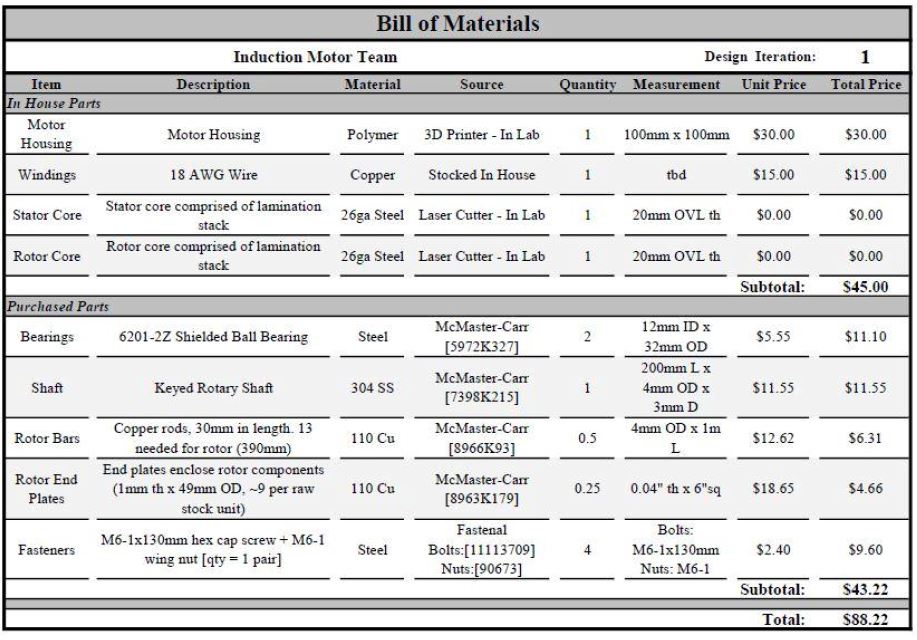
4.3 Bill of Materials
5. Assembly
This section will cover the assembly procsses of the three different prototypes we came up with for this project.
5.1 First Iteration (P1)
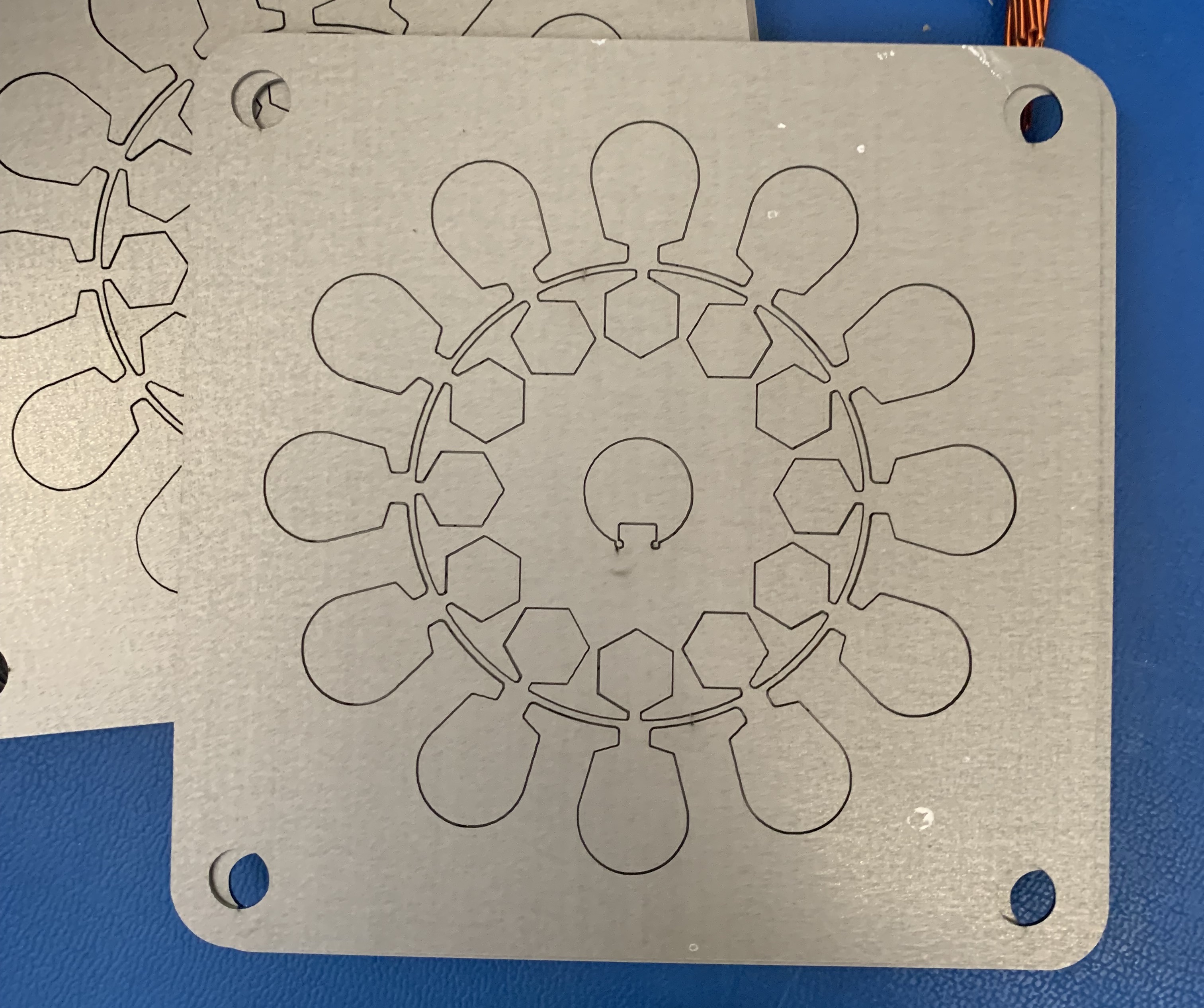
The first task tackled was laser cutting the steel laminations for the stator and rotor. The video below provides a visual demonstration of the rotor laminations being cut using the FabLight 4500 laser cutter in the Grainger Power Electronics and Electric Machines Laboratory on campus. For context, the lamination steel we used was M19 29 gauge steel provided by the client.
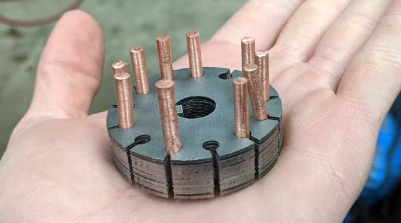
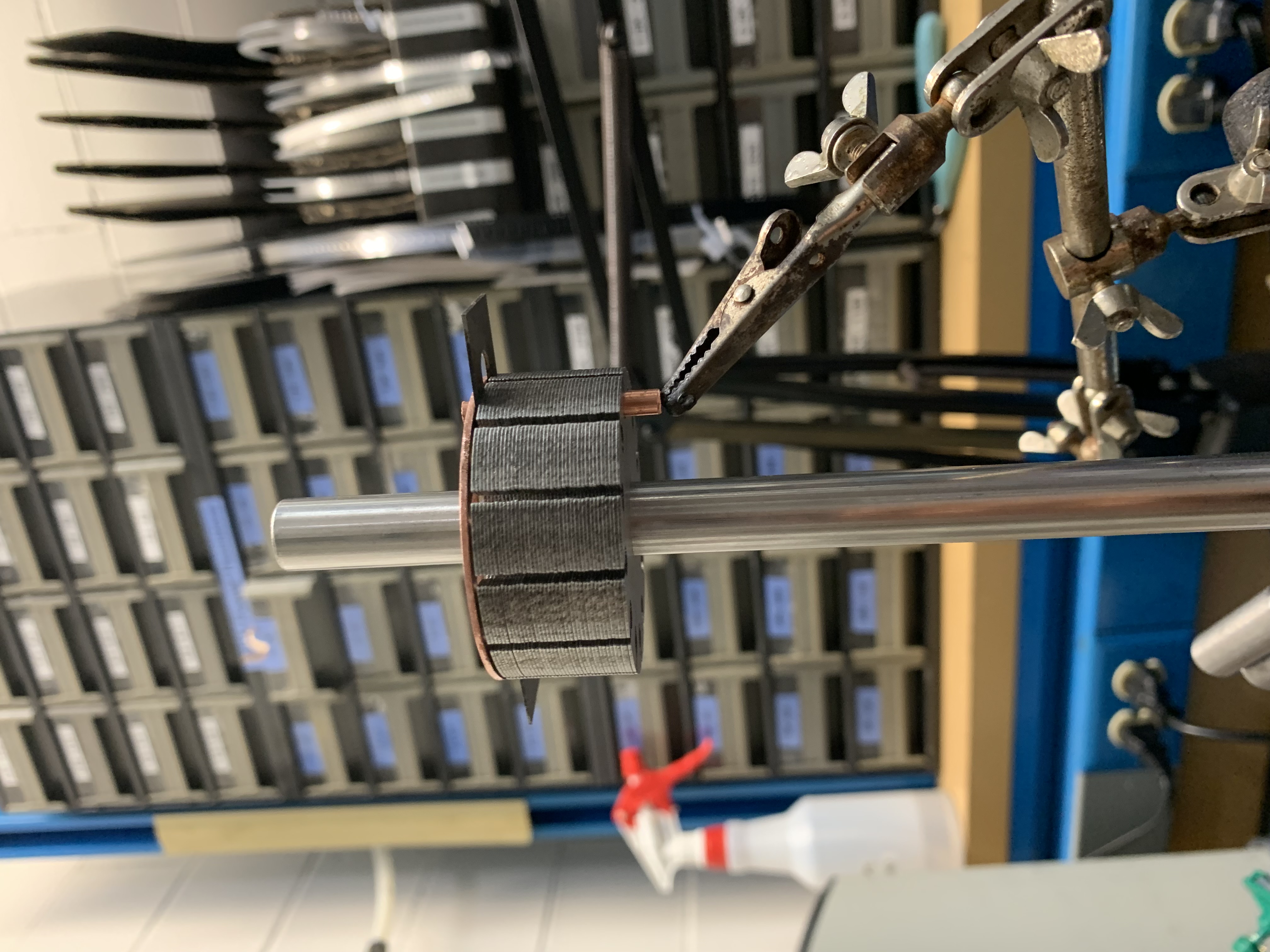
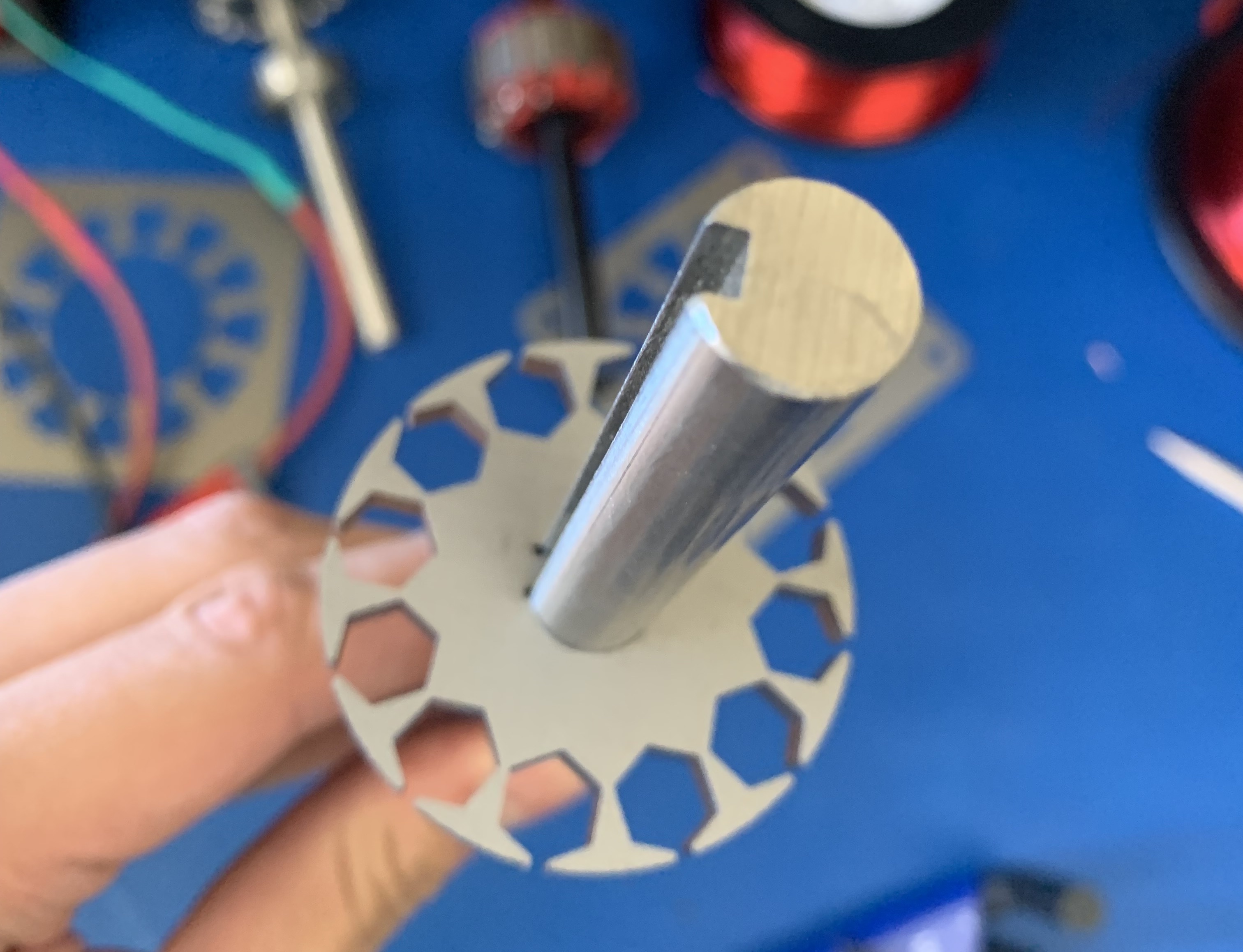
After completing the lamination cutting process, the resulting rotor laminations were inserted and stacked onto the keyed shaft we purchased from McMaster.
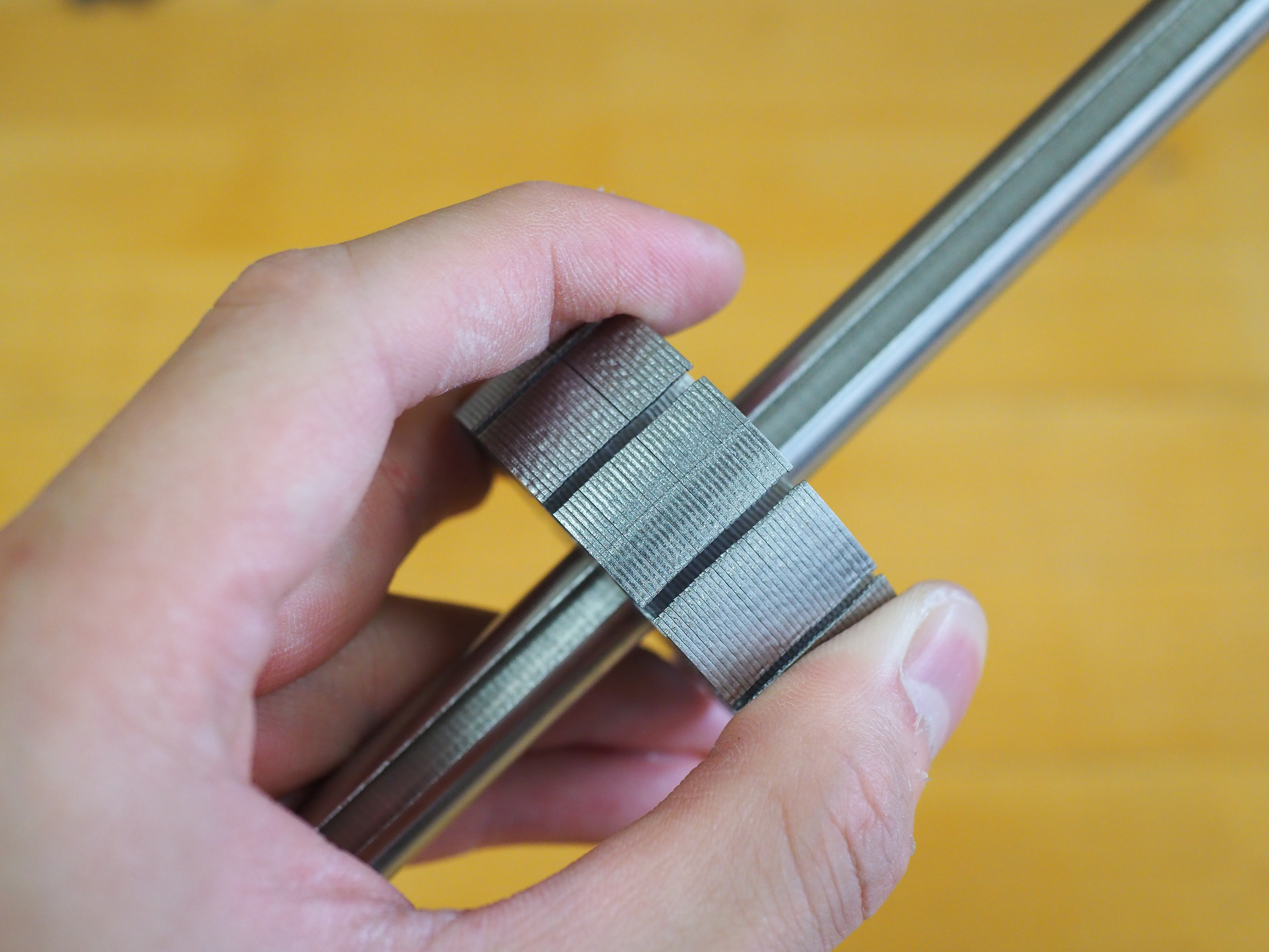
The next task the team did was cutting the copper rotor bars in length. These bars were intended for insertion into the rotor laminations, with copper end rings to be soldered on both sides, effectively creating a short circuit across all the bars. However, during the attempt to insert the copper rotor bars into the laminations, the team encountered resistance in the process. Investigation revealed that the laminations had slight variations in their cuts, leading to a significant misalignment of the copper bar slots. This misalignment can be seen in the image below, and it is clearly visible on the outer surface of the rotor lamination.
After some investigations, it was determined that the problem arose from the absence of tab features being enabled in the laser cutter’s settings during the cutting of the rotor laminations. During the cutting process, nitrogen gas was blasted at the cut to prevent oxidation on the cut surfaces of the steel. Due to the combination of this blasting action and the absence of tab features, the laminations experienced slight shifts with each cut. Consequently, the cuts were inconsistent, resulting in the observed misalignment on the rotor laminations.

After the team figured out the root cause of the failure, the team proceeded to re-cut the laminations with the correct tab settings. Futhermore, additional tolerancing was also allotted to the laminations to ensure the copper bars cut fit through all 43 lamination sheets. Immediate improvement was observed as the copper bars fit into the rotor.
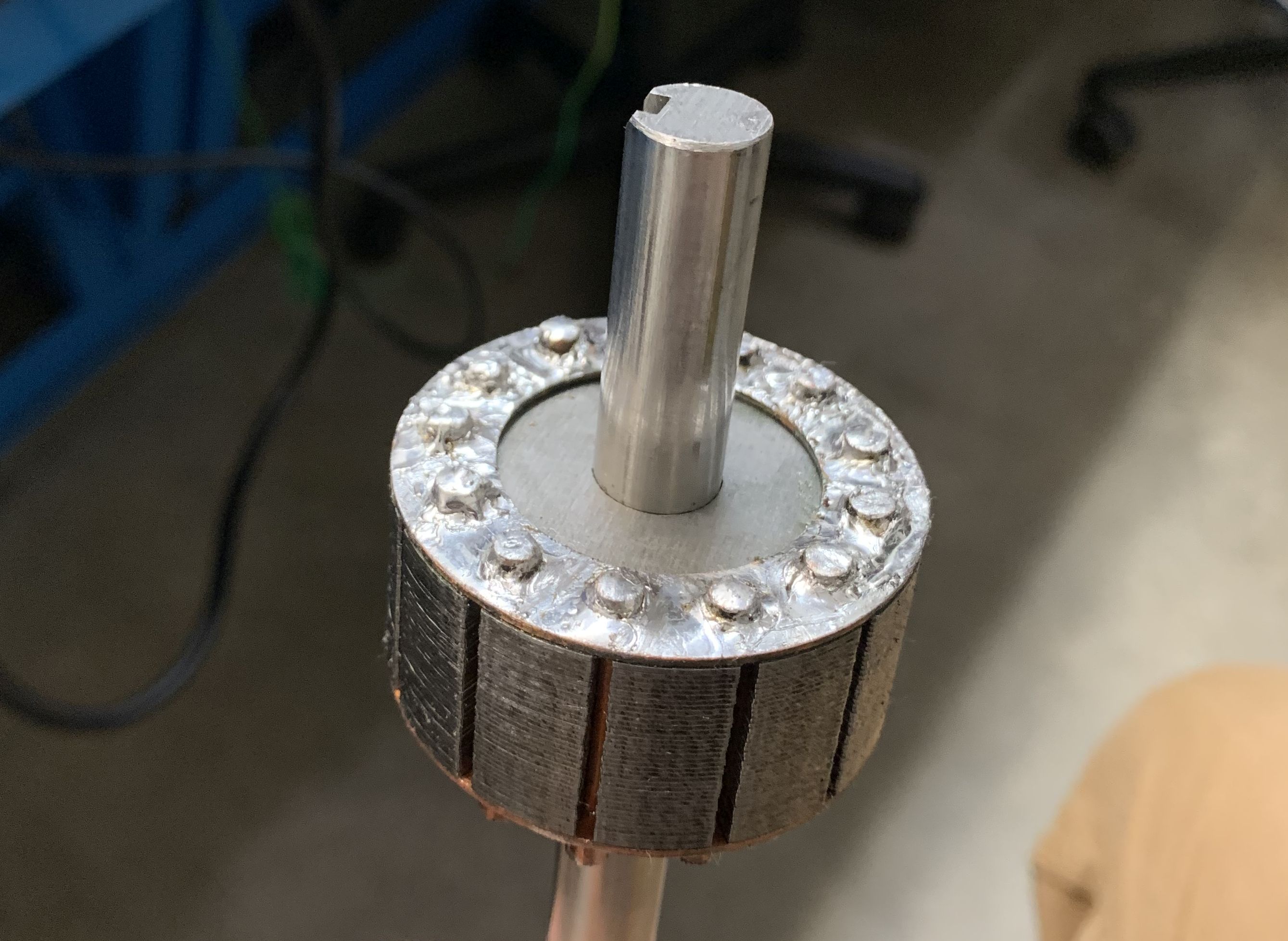
With the issue resolved, the team moved forward with the task of soldering the copper end rings to the rotor bars. Unfortunately, another issue emerged during this phase. With only a low-powered soldering machine avaliable to us, the soldering process took approximately 3 hours. This extended duration primarily stemmed from the larger thermal mass the soldering iron needed to heat up in order to attain the necessary temperature for proper solder melting. This is not optimal for a machine that is supposed to be easily assembled but will be considered as a potential area for improvement in future prototypes.
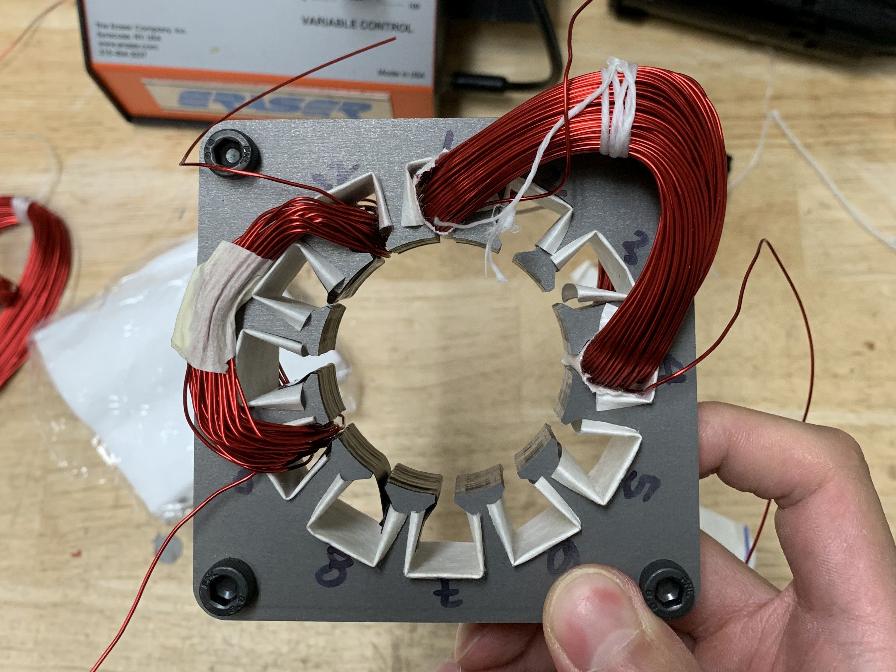
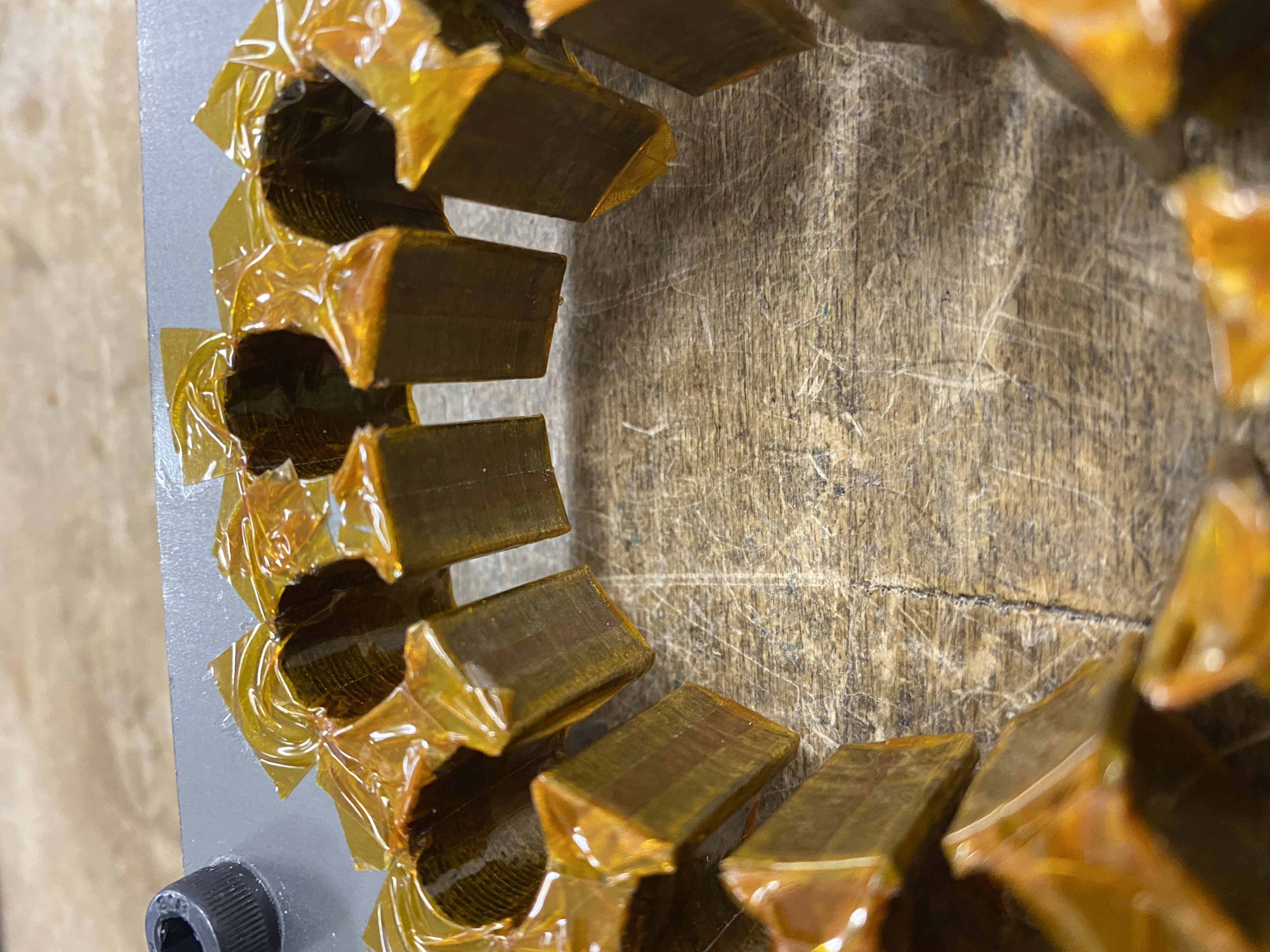
With the rotor done, time to move on to the stator. The resulting stator laminations were first stacked and secured together using four M6 fasteners. Following this step, insulation papers were inserted into the stator slots. These insulation papers play a critical role by ensuring electrical insulation, effectively preventing copper wires from coming into contact with the steel laminations and creating potential short circuits.
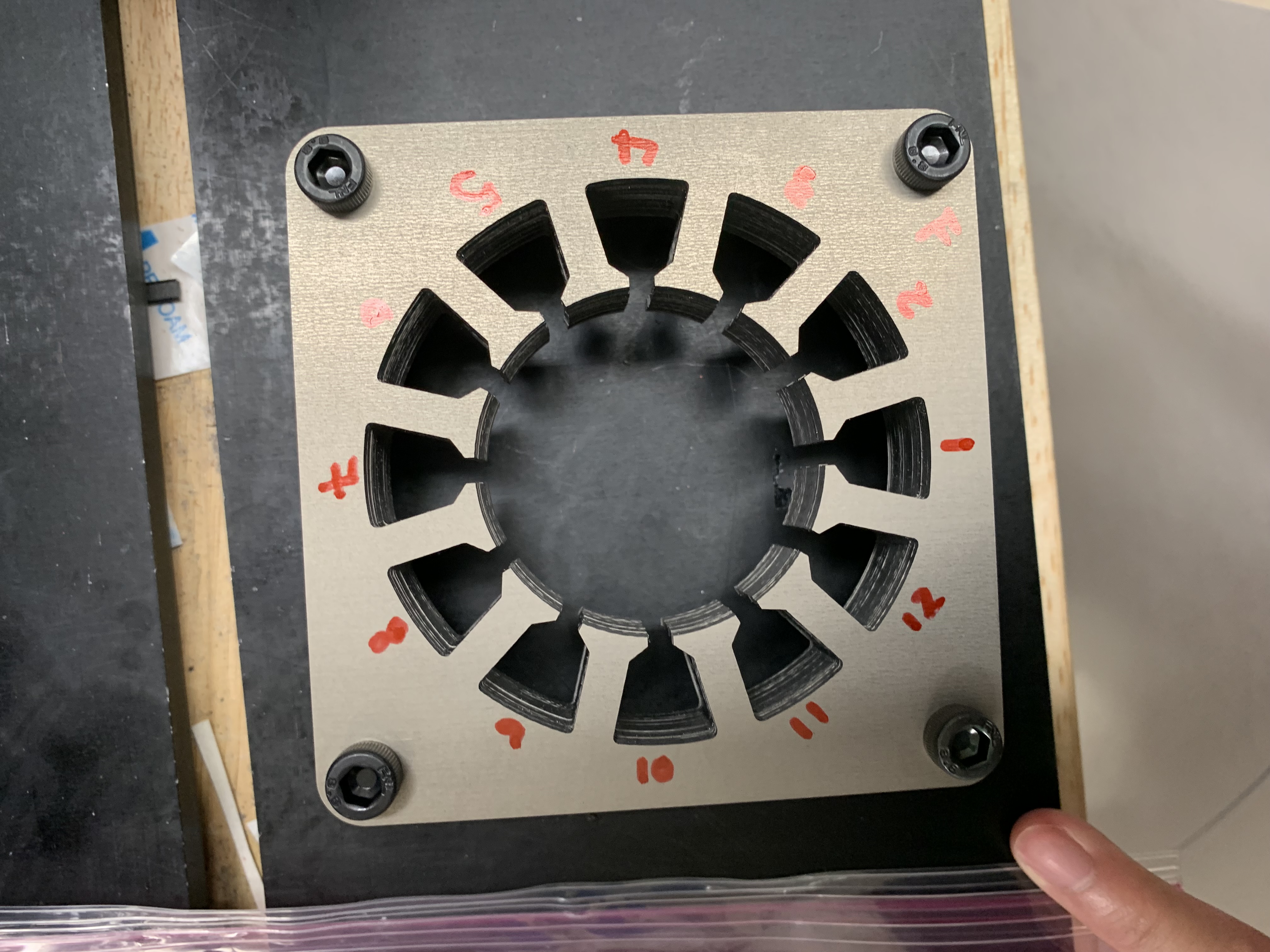
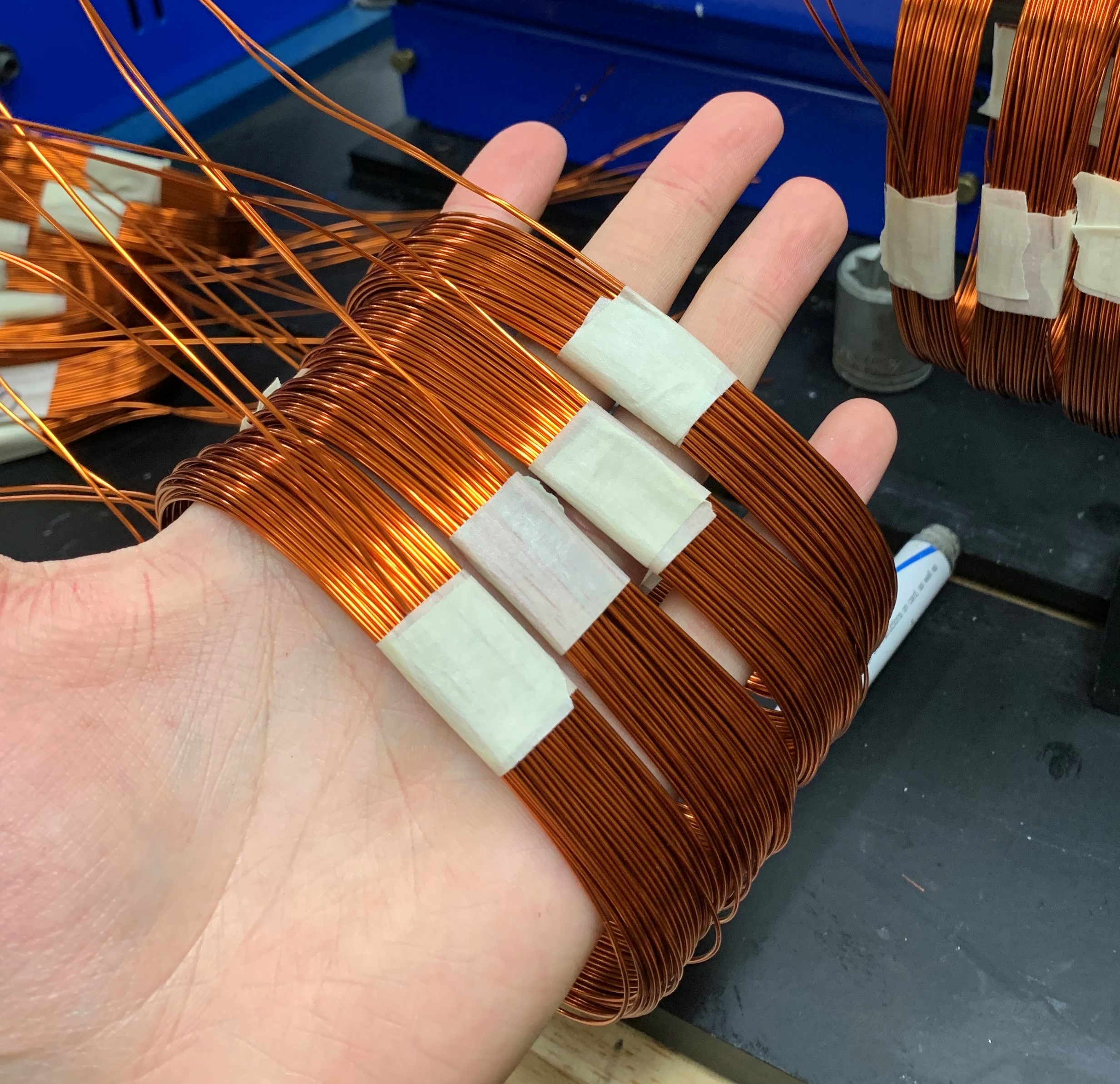
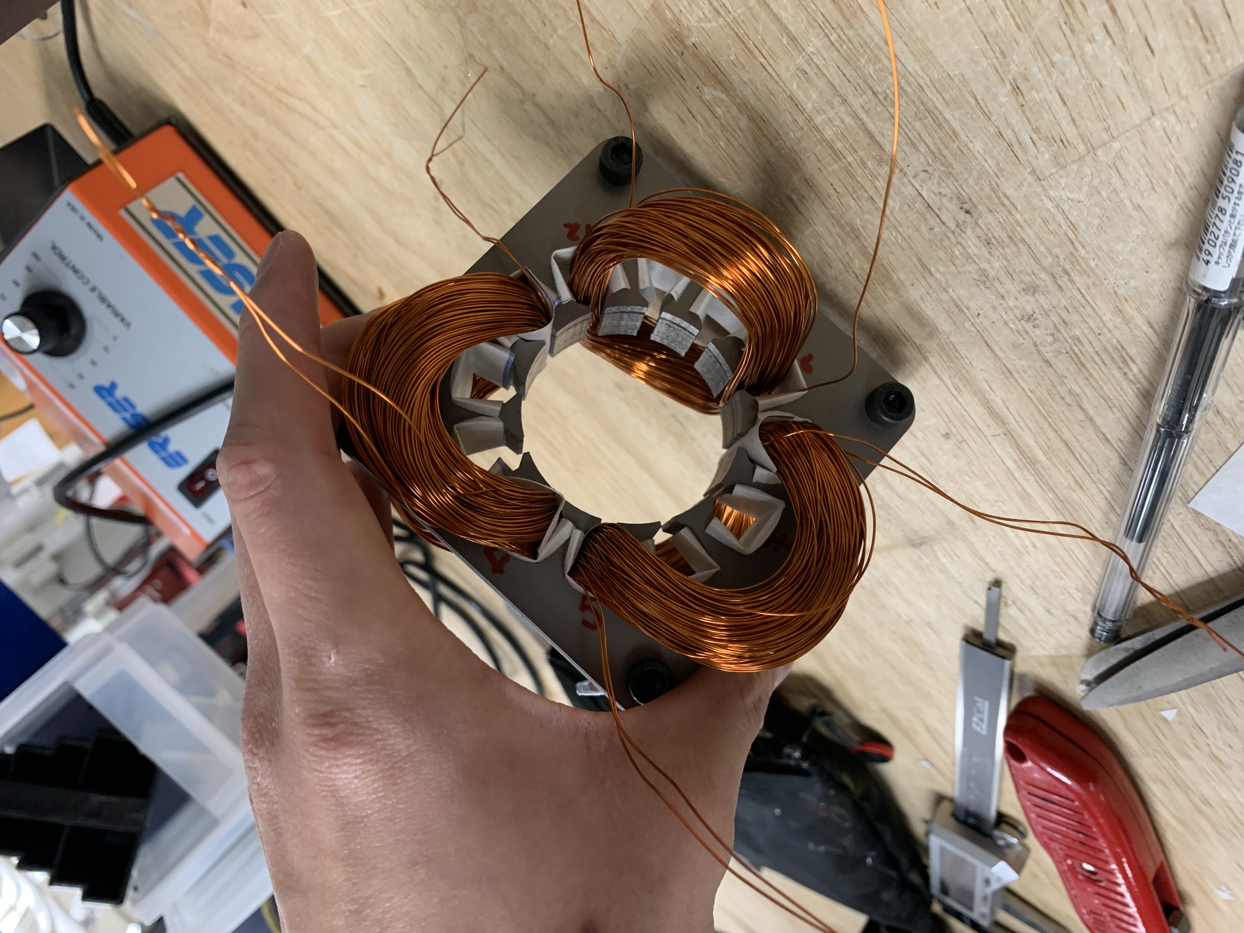

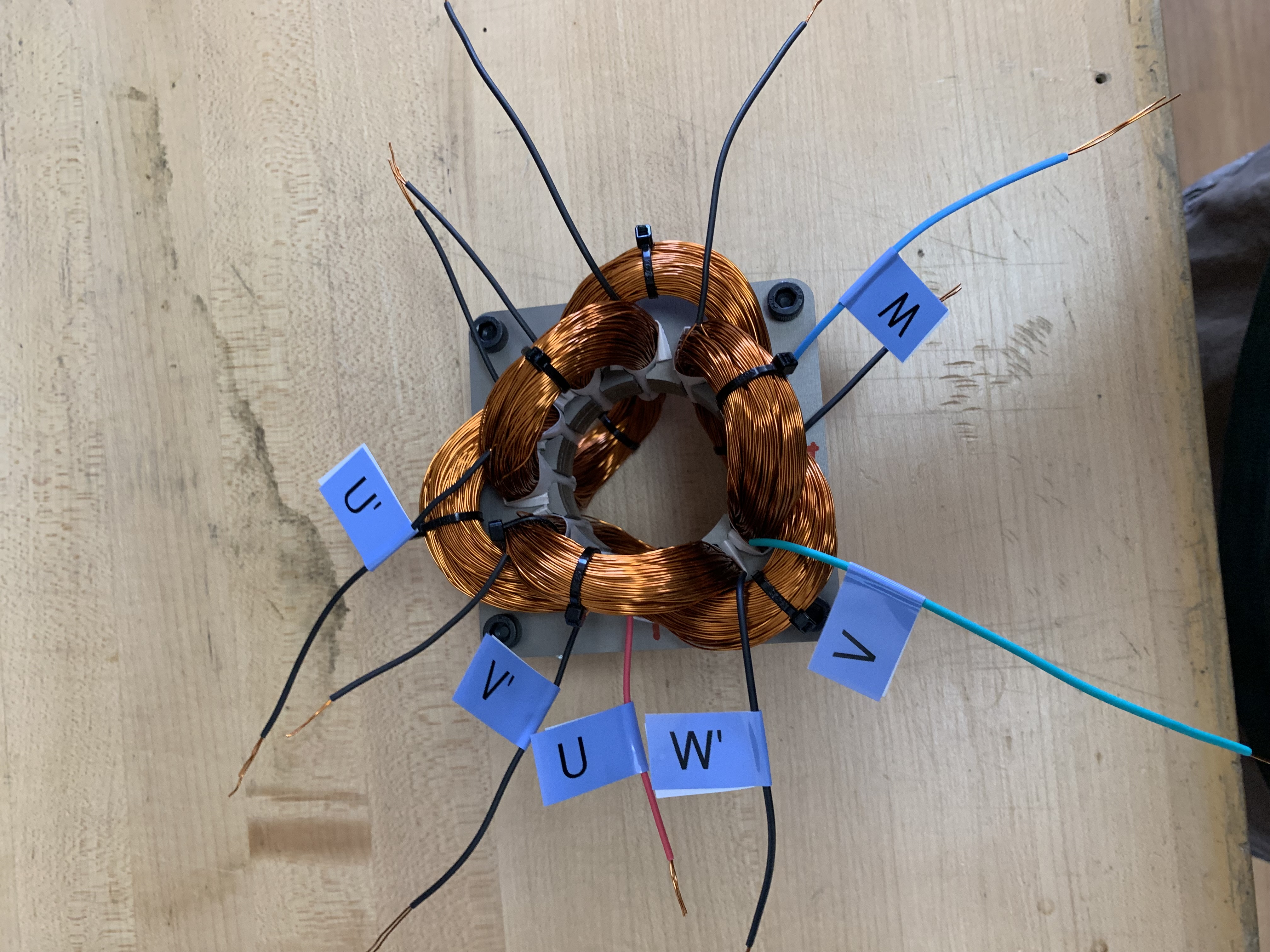
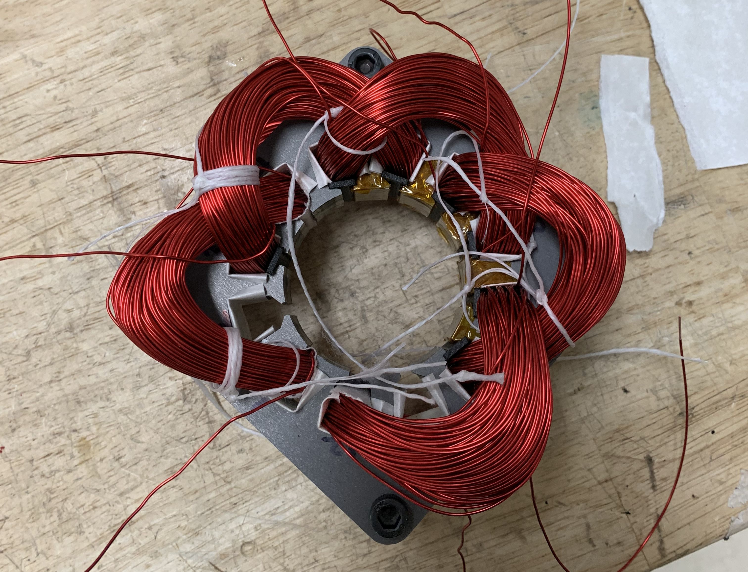
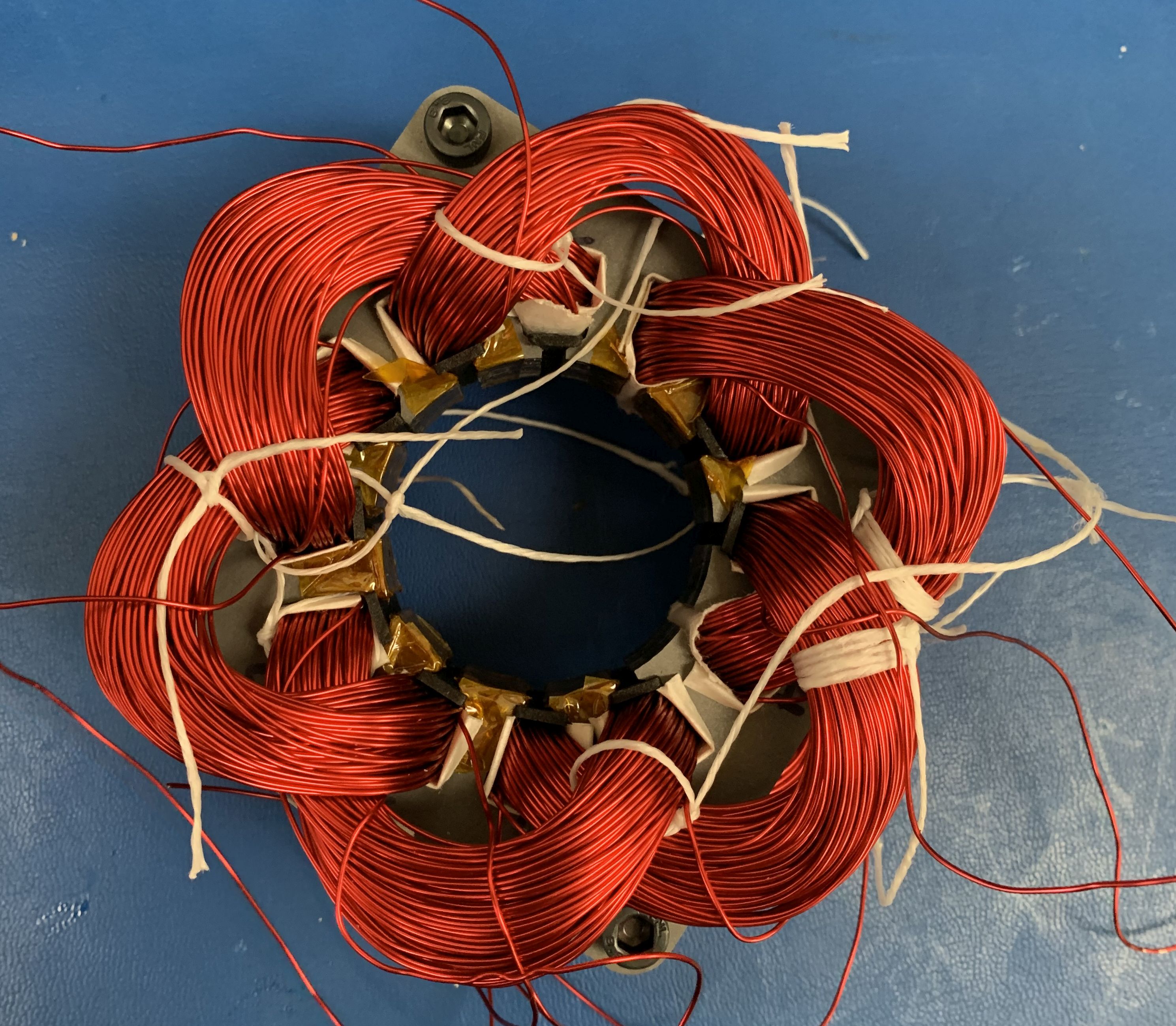
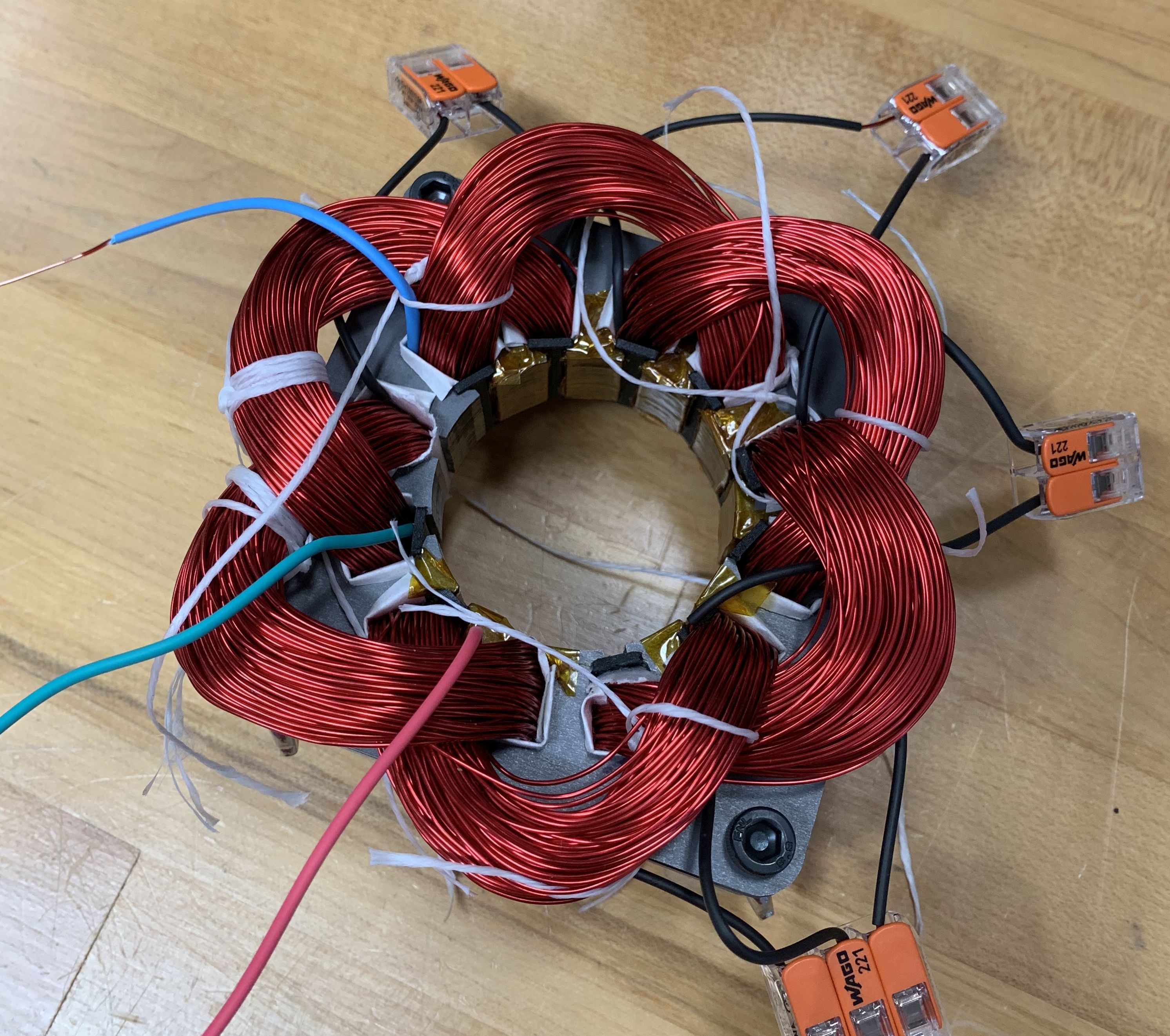
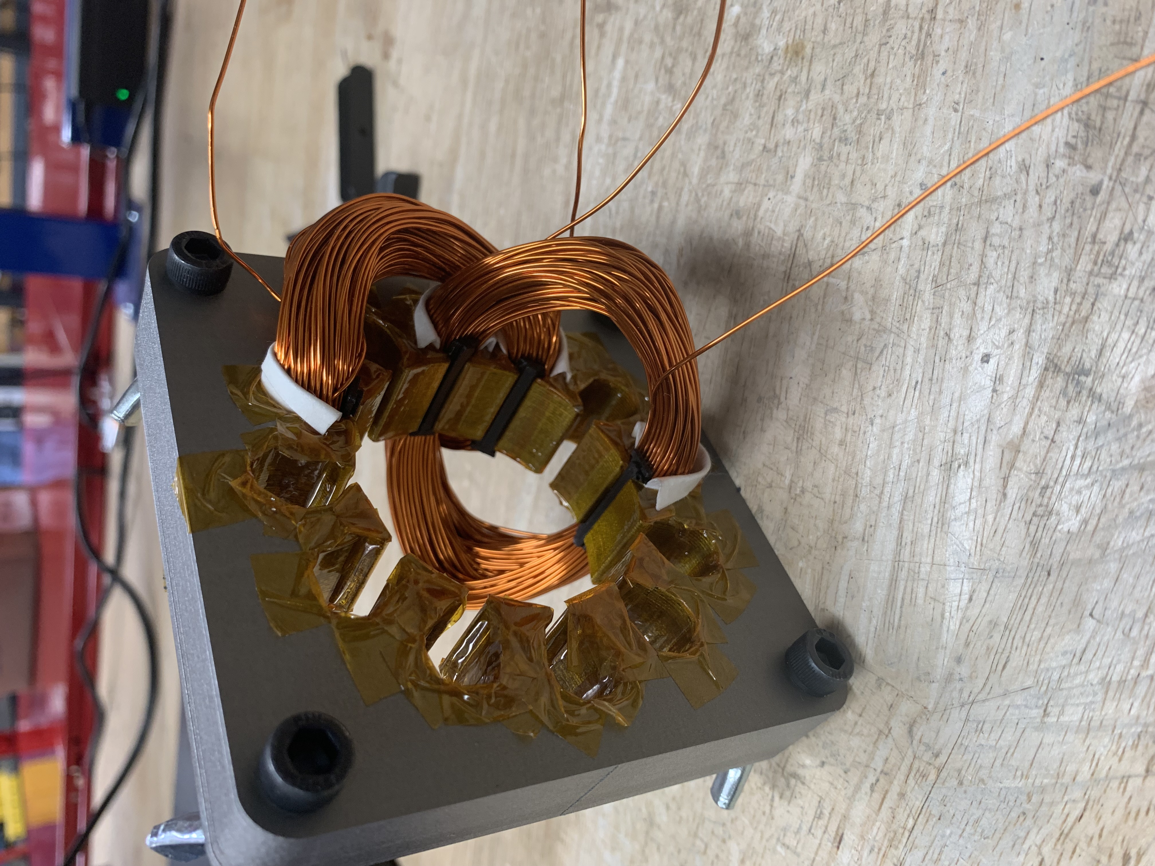
After about an hour or so, all stator windings were sucessfully installed. As can be seen in images below, there are total of six coils and are connected in wye configuration. Images below shows the fully wound stator with the rotor inserted.
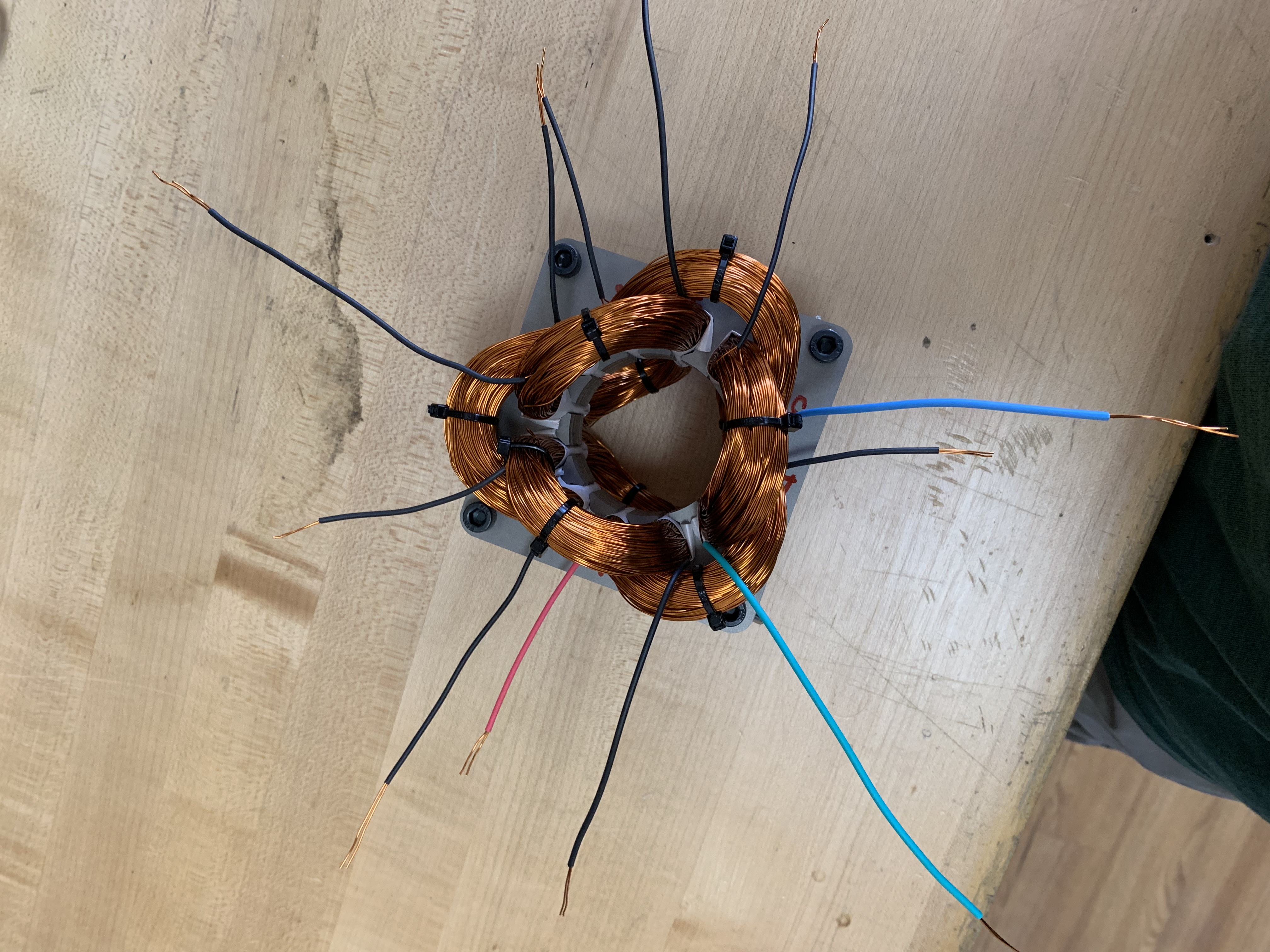
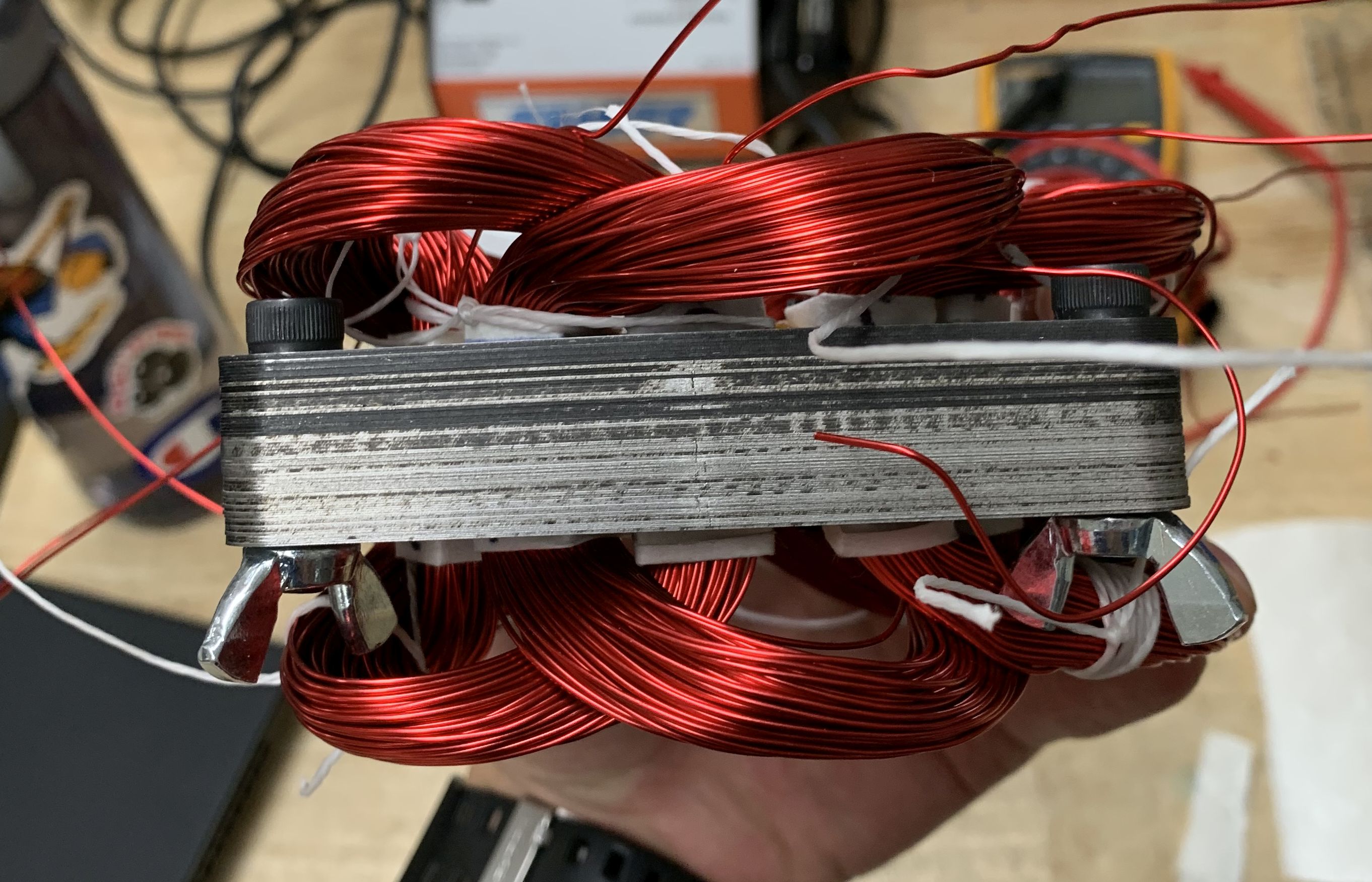
A side view showcasing the stator with the inserted coils up against a McMaster-Carr catalog reference. Notably, the team recognizes the need for improvement in the overall assembly’s thickness for the subsequent iteration.
NOTE: ![]()
![]()
![]() First prototype was a sucess!
First prototype was a sucess! ![]()
![]()
![]()
5.2 Second Iteration (P2)
Based on the feedback and lessons learned from building the first prototype, we came up with several improvements we hoped to achieve for our second iteration prototype.
- Improve rotor assembly, specifically on the soldering part of the copper endplate.
- Reduce overall assembly height, particularly the end-turns of the coils.
- Come up with new method of preventing copper coils from getting into the airgap.
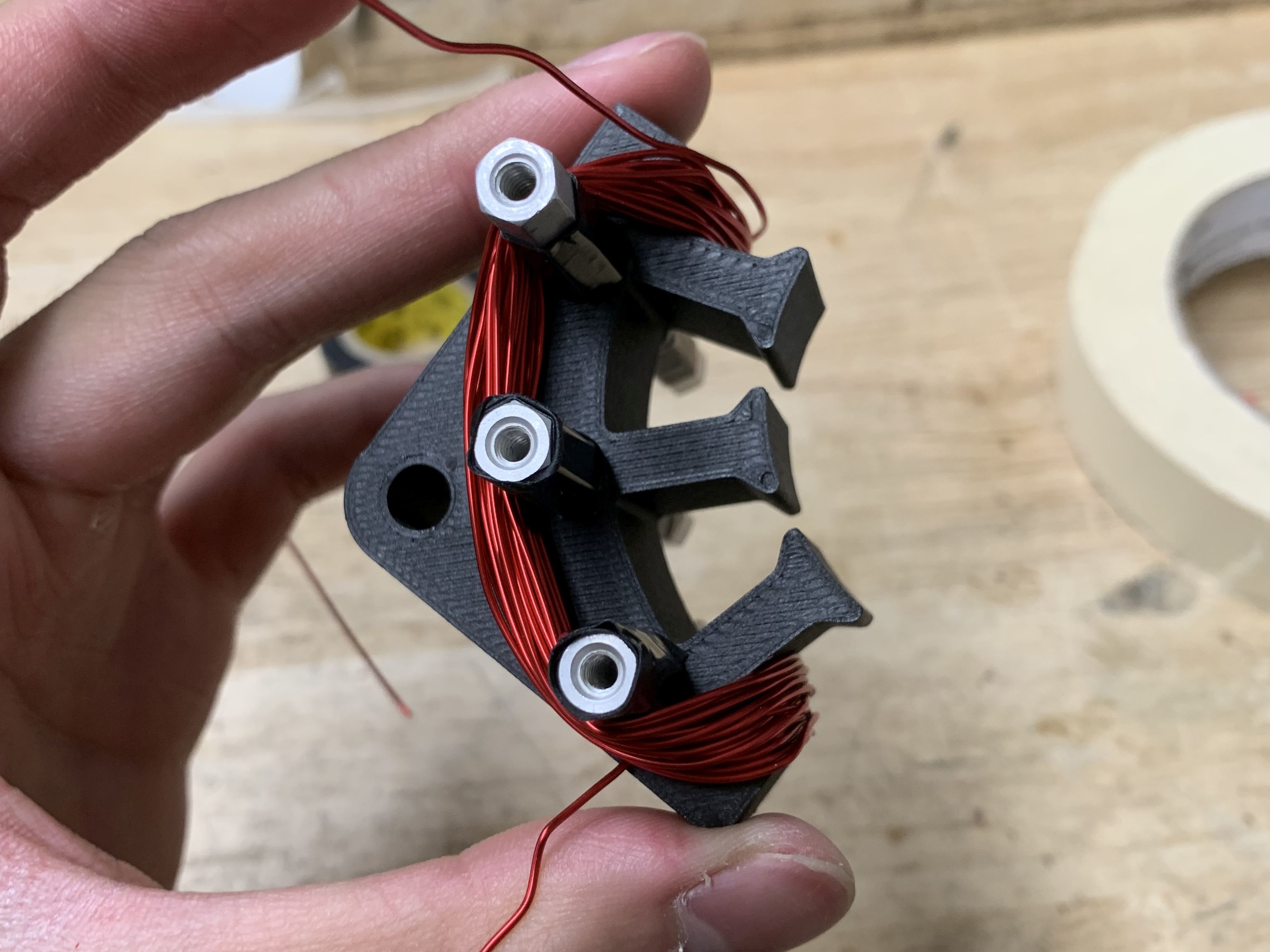
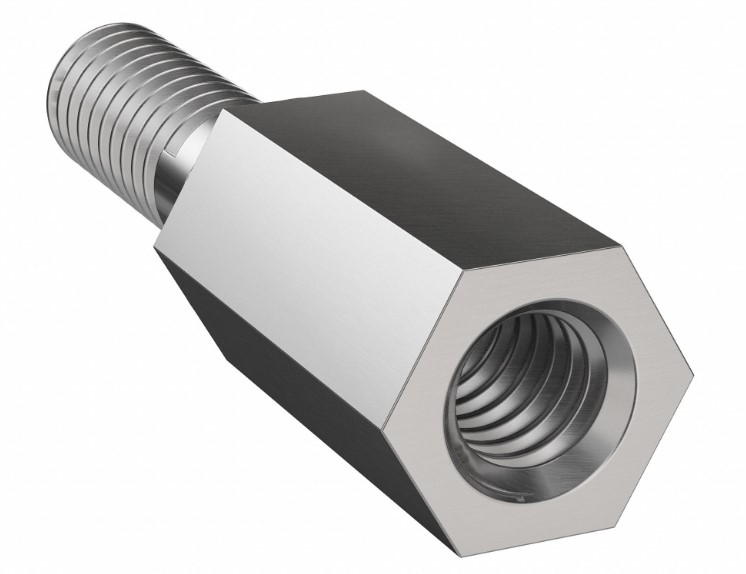
We made an attempt to utilize a 3D printed winding jig to shape the coils and reduce the length of their end-turns. The images below depict metal bars on the jig, which are aluminum standoffs.
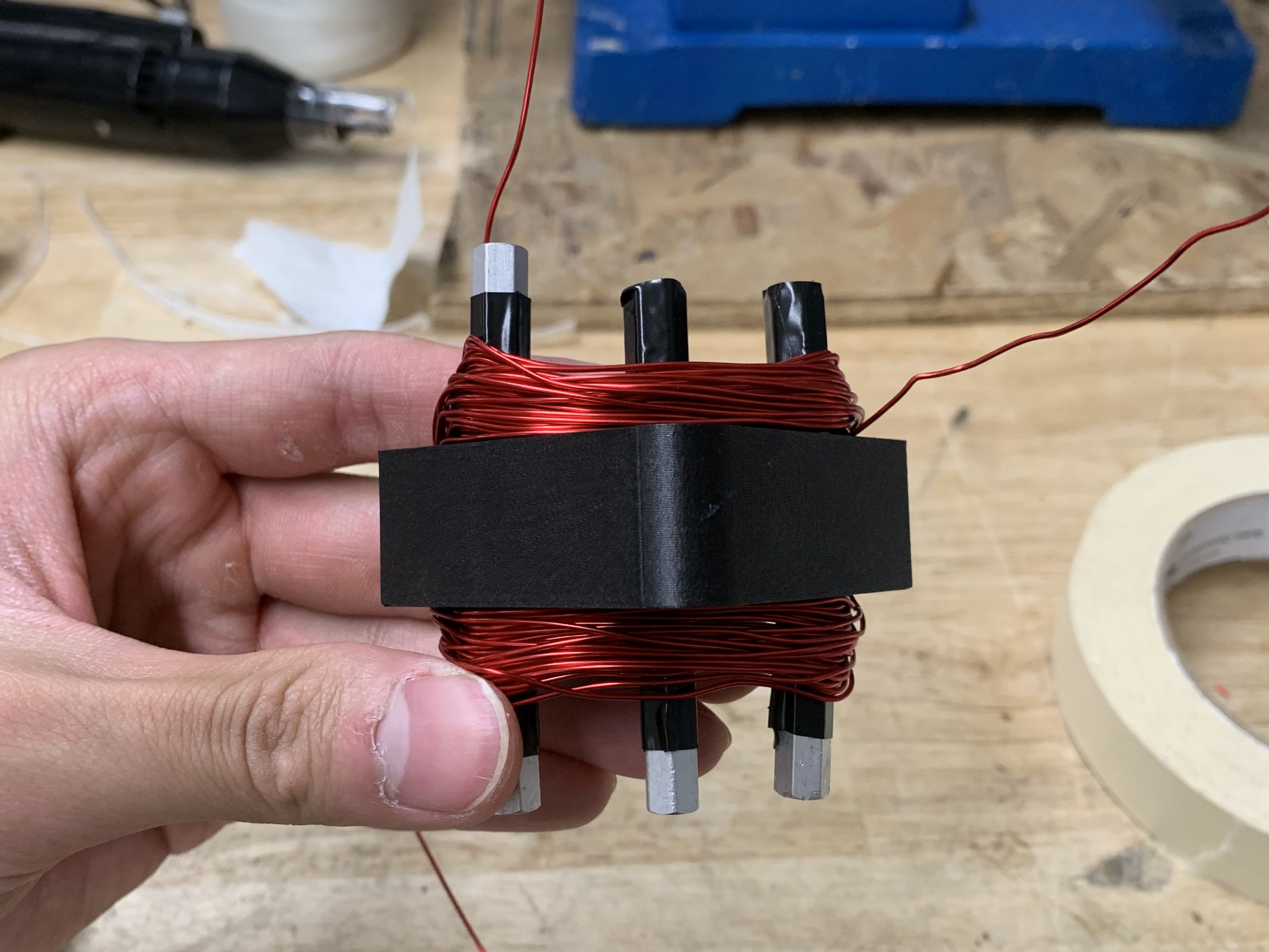
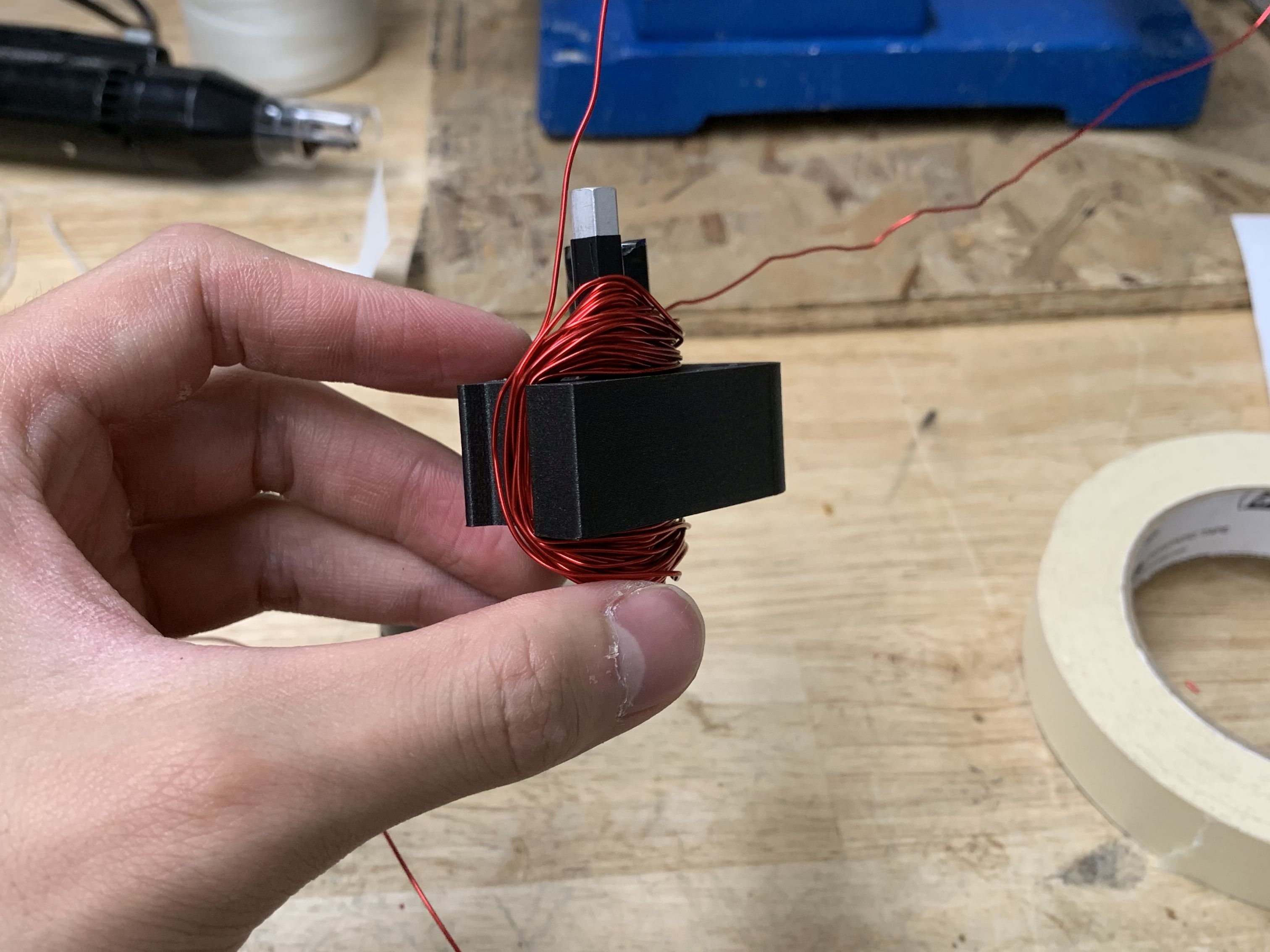
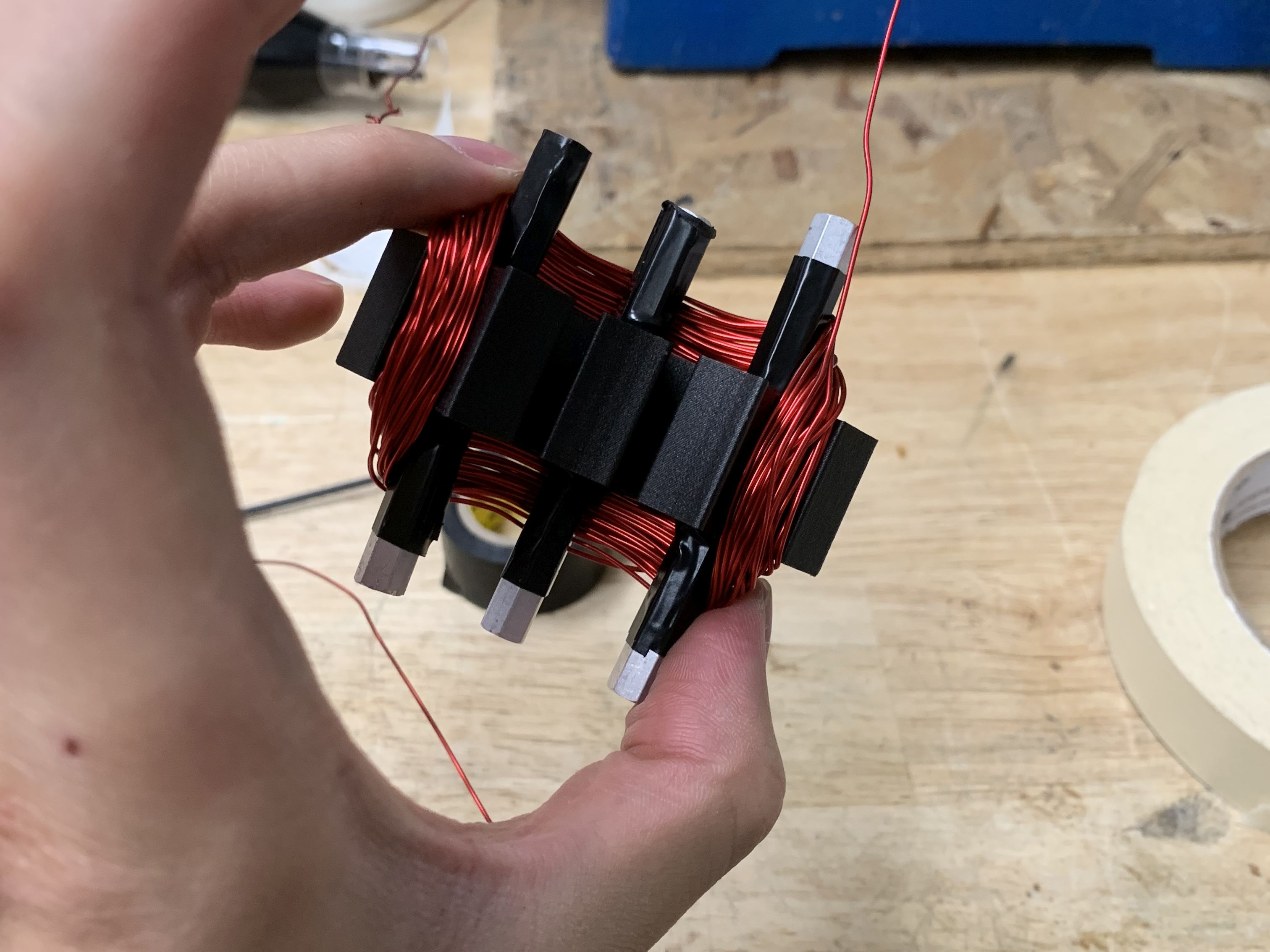
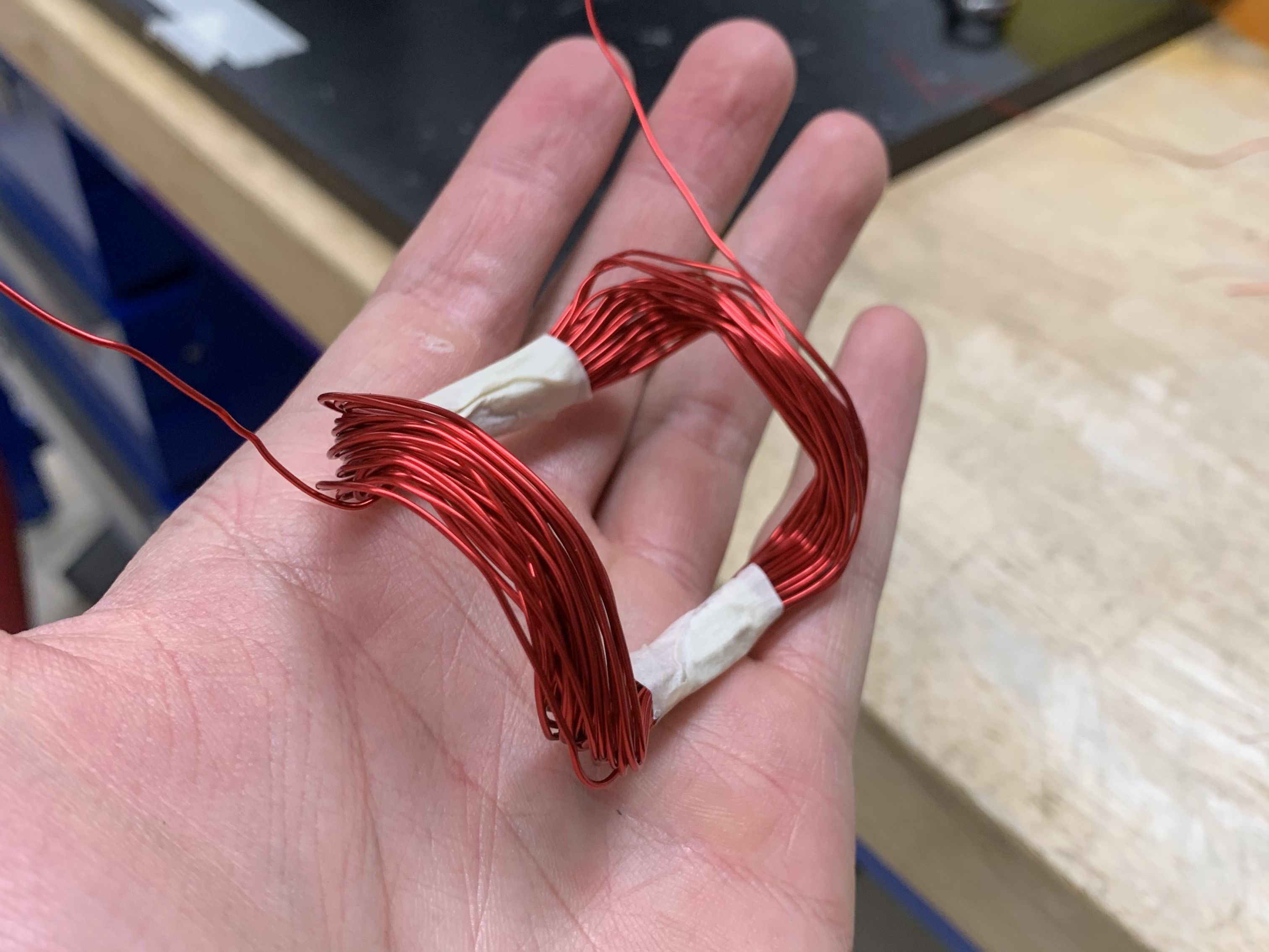
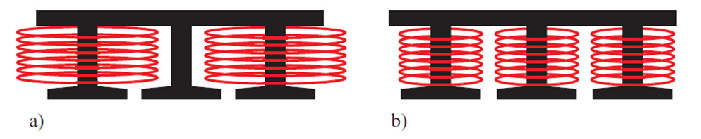
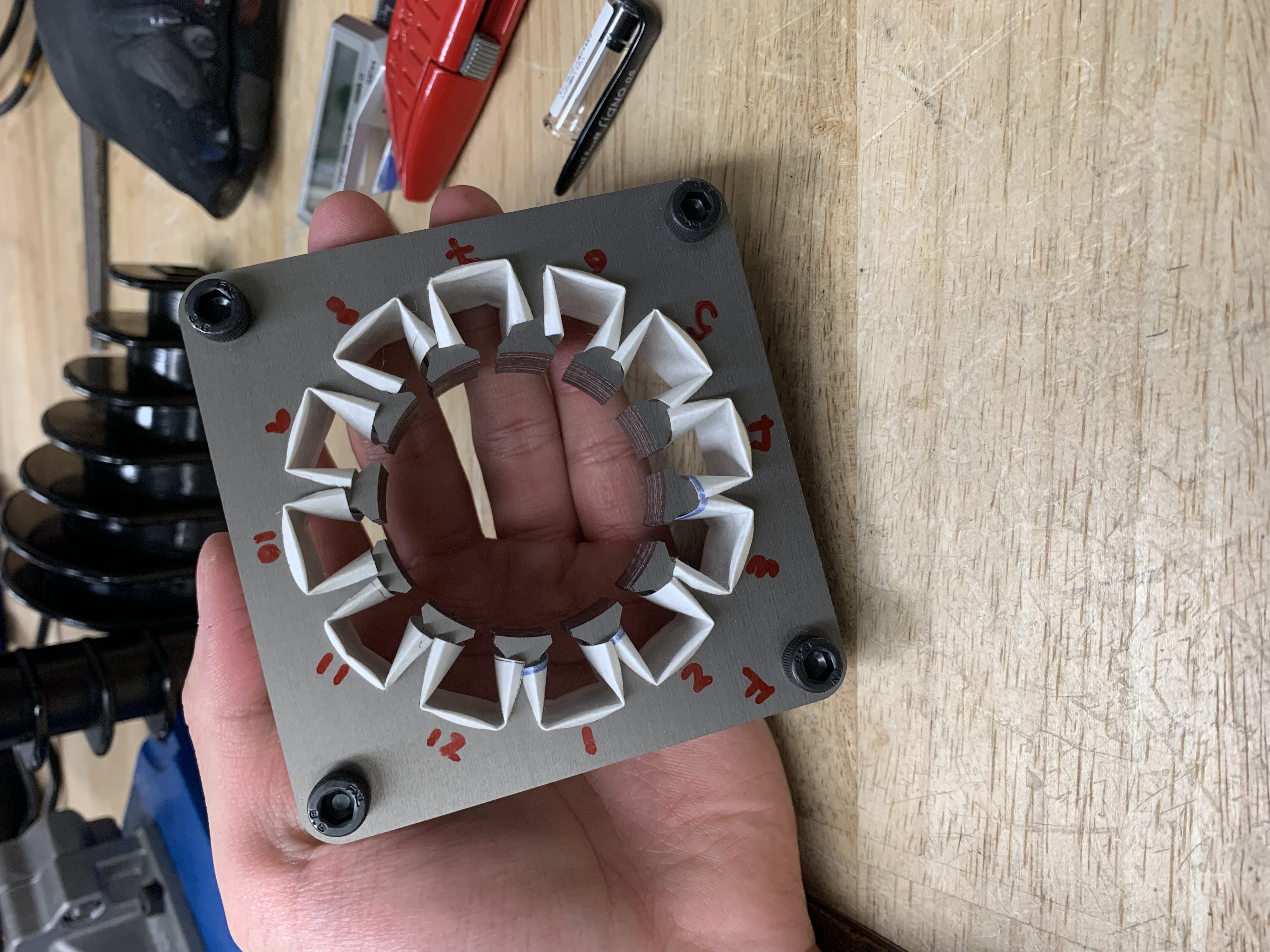
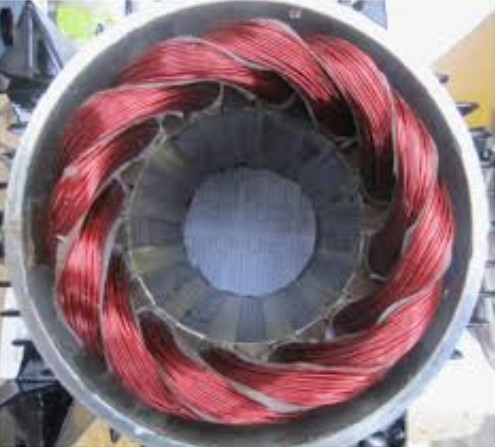
The team made several attempts to manufacture additional coils using the 3D printed jig; unfortunately, the outcomes fell short of the team’s expectations. The coils produced with this method proved considerably more challenging to insert, as opposed to those created through the manual winding machine. As the team was seeking methods to improve on the design, our client recommended employing an overlapping endturn pattern for the stator windings over the pattern used in the initial prototype. This overlapping pattern can be seen in the example shown below.
Another design improvement the team hoped to implement was adding 3D printed slot inserts to preventing copper coils from getting into the rotor airgap.
In the second iteration, the team successfully lowered the height of the stator assembly by adopting the overlapping end-turn pattern during the winding process. Furthermore, the team devised a solution to prevent the copper coils from entering the rotor air gap by 3D printing slot inserts. Unfortunately, due to technical difficulties with the laser cutter in the lab, the team faced obstacles in producing new rotor laminations. This setback impacted our timeline as we worked towards improving the manufacturability of the rotor assembly.
5.3 Third Iteration (P3)
Once the laser cutter was operational again, the team wasted no time in initiating work on our third prototype. For this final iteration of the induction machine prototype, our primary focus was on enhancing the rotor design.
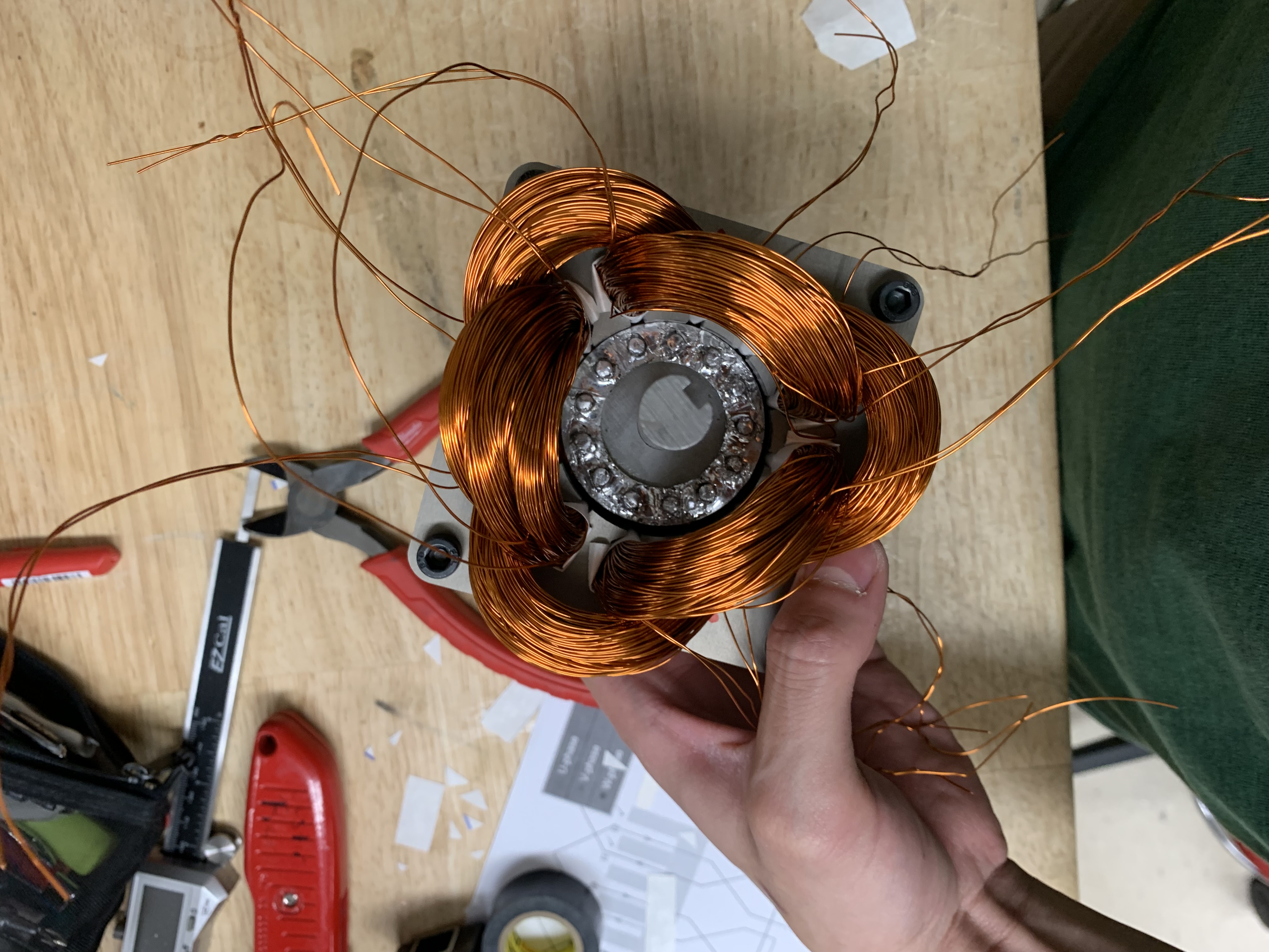
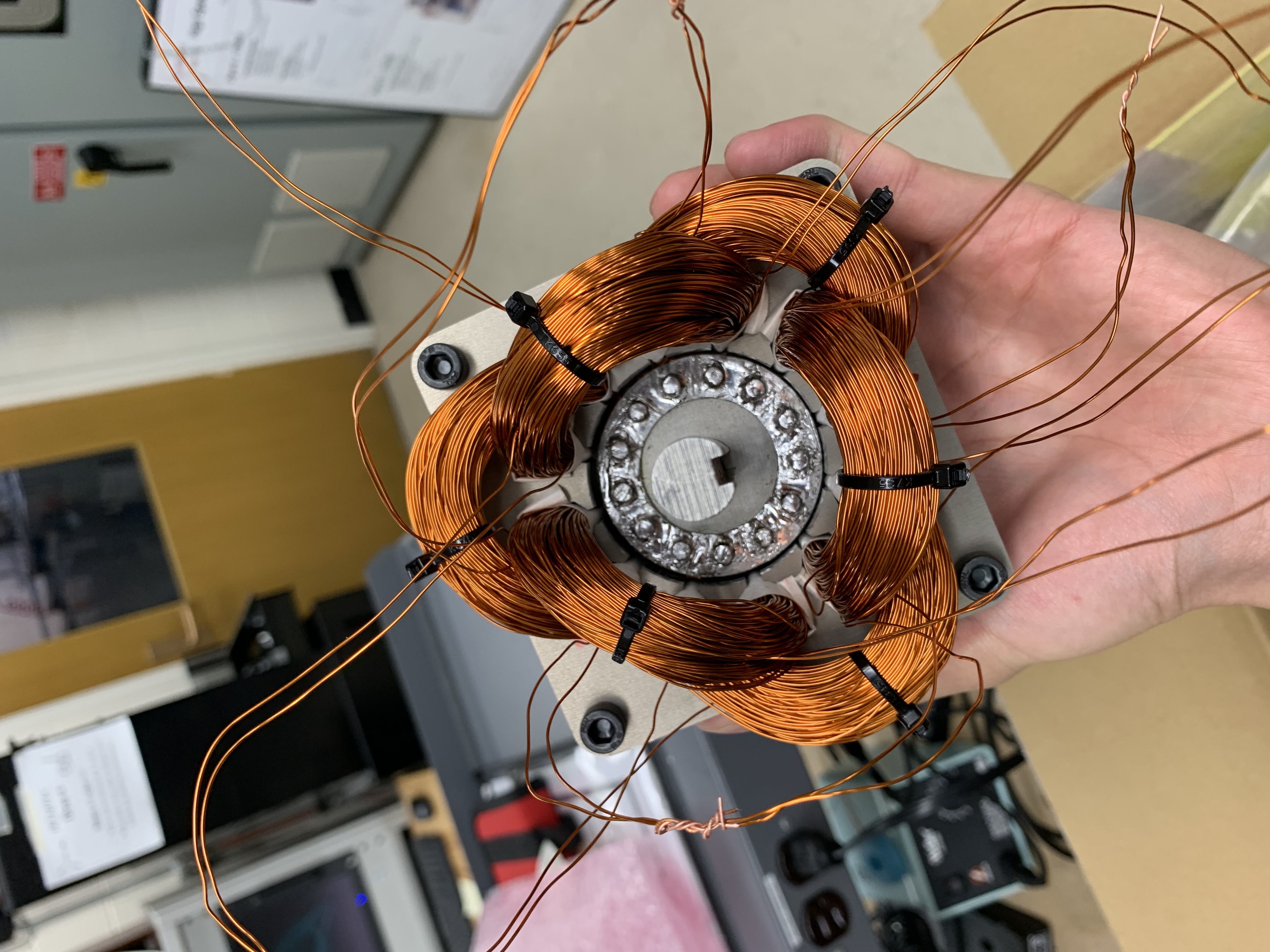
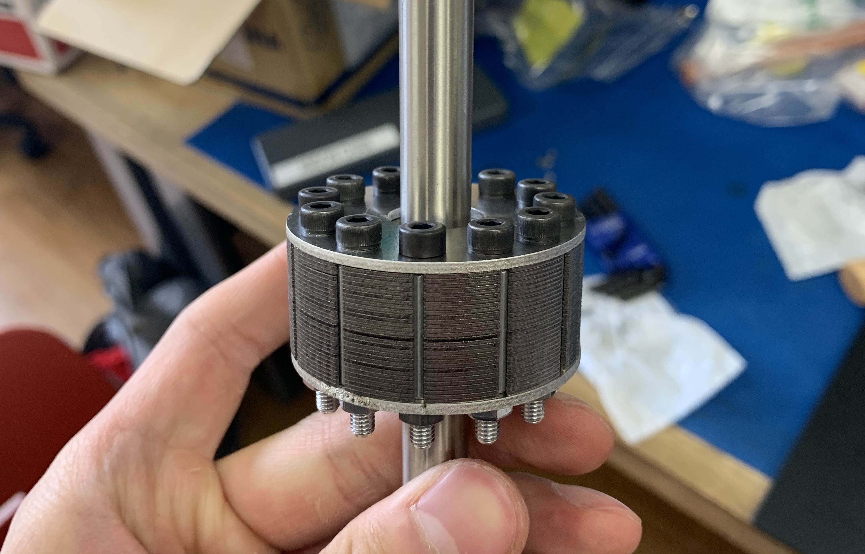
In the prior rotor design, users had to solder the copper bars to the copper endplate to complete the squirrel cage structure. In this iteration, the team aimed to develop a new design that eliminated the need for soldering, relying instead on mechanical methods to secure the squirrel cage structure. When searching for new solutions, the team conceived the idea of replacing the copper bars with aluminum standoffs, a readily available component within the lab and commonly used in mounting electronic circuit boards (ECBs).
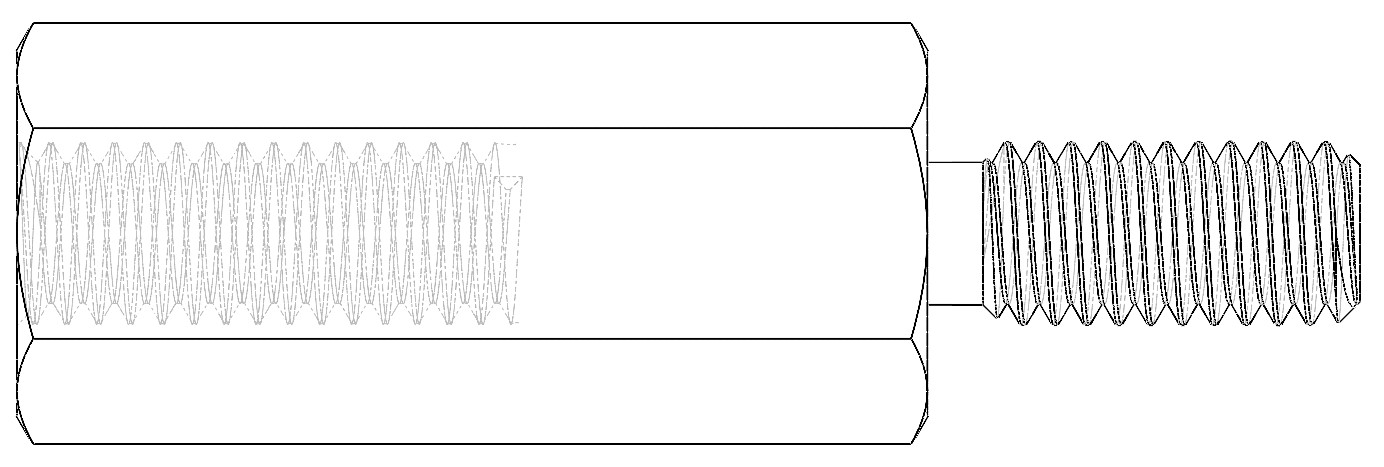
In order to substitute the copper bars with aluminum standoffs, the team had to estimate the resistance values of these aluminum standoffs to match the copper bar values. Given copper has an electrical conductivity of approximately three times higher than aluminum, this implies that the cross-sectional area of the aluminum components needs to be three times larger to achieve the same resistance. Consequently, accommodating all the required aluminum standoffs in the design became challenging.
As a result, one of the design decisions the team had to make was to reduce the number of standoffs from the original design of 13 to just 11. This alteration in the design probably led to a reduction in the torque output and hence overall efficiency. Though, given that manufacturability was our priority in this project, the team was comfortable with implementing such changes to the prototype design.
One particularly important aspect the team had to exercise extra caution with was ensuring that the core of the aluminum standoff is not hollow during the selection process.
Turning our attention to the stator. Following the successful implementation of the overlapping end-turn pattern in the second prototype, the client challenge us to further reduction of the coil length. This reduction is primarily motivated by cost considerations, as enameled copper wire can be expensive, and decreasing the coil length can provide cost savings for each motor.
One of the major challenges encountered when attempting to reduce the length of the coils was the difficulty in bending the end-turns. When the coils were tightly packed together, shaping them became exceptionally challenging. The team noticed by using a mallet and gently tapping the coils, the shaping process became considerably more manageable. Thus, with this technique and some patience, the team succeeded in successfully inserting all six coils. The reduction in coil length is about 30% from the previous prototype.
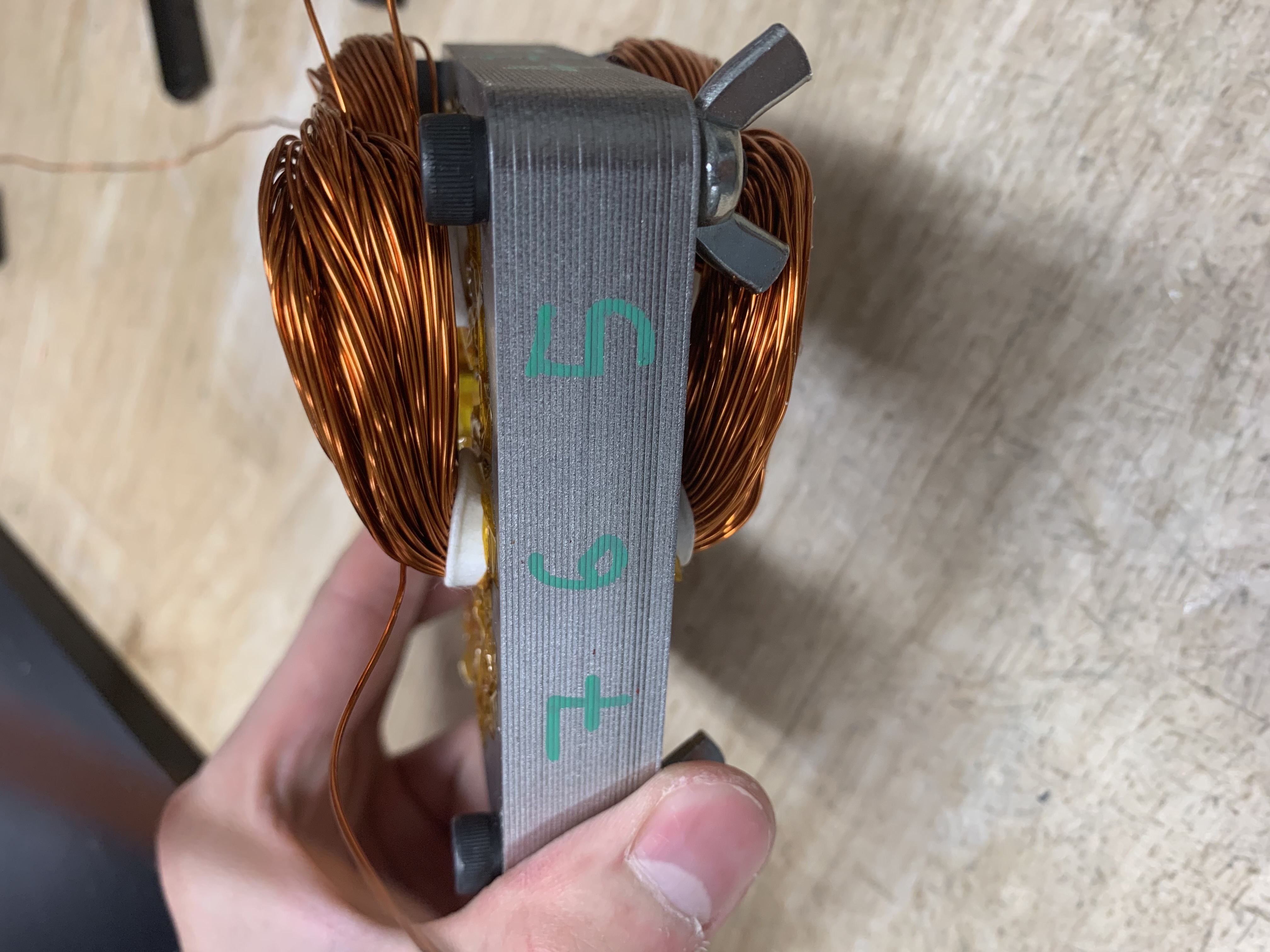
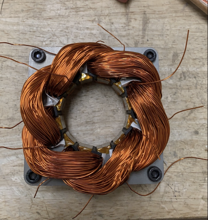
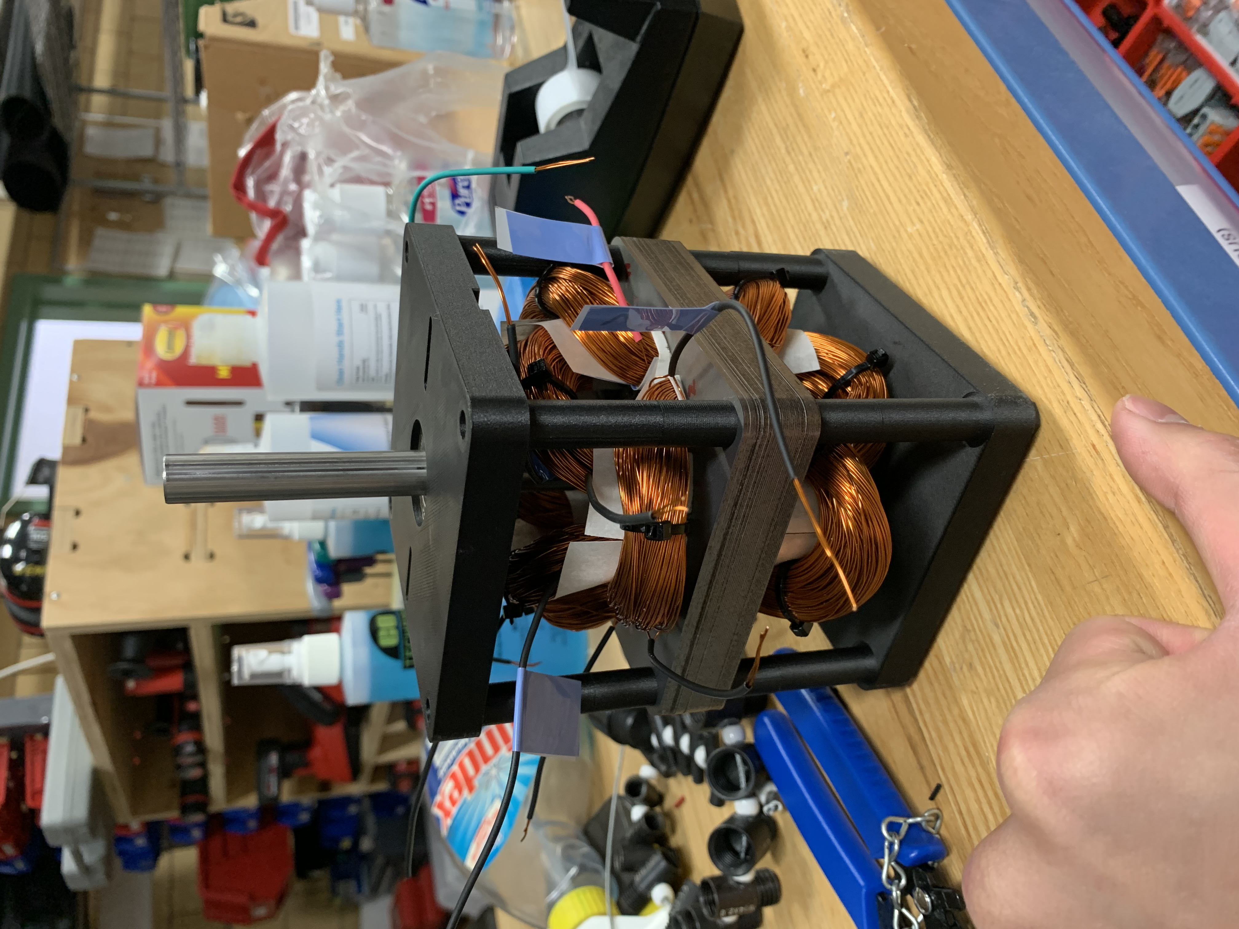
Image below shows the height of the finished stator to be approximately 6cm (about 2.36”). To provide a prespective, the first prototype is slightly taller than a McMaster-Carr catalog and is about 3.25” in height. That is close to 30% in height reduction.

6. Summary and Final Thoughts
Well, in summary, I would conclude this senior design project as a success. We took on the challenge of creating a small-scale induction machine tailored for educational purposes in a college course. Our mission was clear: to develop a teaching tool that would equip young engineers with hands-on experience in motor constructions as they transition into the industry.
The team worked tirelessly in coming up with three different prototypes for our client. I must also admit throughout the design and building process I myself have made countless mistakes specifically with the rotor lamination in the third prototype lol. Regardless, I have learned a lot from this project and the mistakes I have had made along the way.
All in all, I am satisfied with the way how things turn out and the teamwork we put in. Needless to say, the client was also pleased with the result!
7. Documentation
7.1 CAD Files
For those who are interested in the design, feel free to take a look at the CAD model in the Box link below. All models were created in SolidWorks.
7.2 Instructional Manual
8. References
[1] D. W. Knight, L. E. Carlson, and J. F. Sullivan, “Staying in engineering: Impact of a hands-on, team-based, first-year projects course on student retention,” ASEE Annu. Conf. Proc., pp. 10037–10047, 2003.[2] M. Kostic, “Effects of Voltage Quality on Induction Motors' Efficient Energy Usage,” IntechOpen, 14-Nov-2012. [Online]. Available: https://www.intechopen.com/books/induction-motors-modelling-and-controleffects-of-voltage-quality-on-induction-motors-efficient-energy-usage.
[3] U.S. Department of Energy: Industrial Technologies Program, “Improving Motor and Drive System Performance :,” Ind. Technol. Progr., pp. 3, 45, 46, 2008.