
0. Overview
This is a design summary of a test fixture that is capable of measuring change in linear forces for a linear electric machine. This design utilized the precision movement of the milling table of a HAAS CNC machine for conducting measurements. To increase user-friendliness and interchangeability, optical breadboards are used as the primary mounting surface for the linear machine.
Testing of the linear electric machine and experimental results collected using the designed test fixture were published in the following paper in IEEE.
A. Khamitov, J. Swanson, J. Van de Ven and E. L. Severson, "Modeling, Design, and Testing of a Linear Electric-Hydraulic Conversion Machine for Electrification of Off-Highway Vehicles," in IEEE Transactions on Industry Applications, vol. 57, no. 3, pp. 2449-2459, May-June 2021, doi: 10.1109/TIA.2021.3066084.
1. Background
A PhD student in lab designed and prototyped a dedicated linear machine for a piston actuator for off-highway vehicle electrification. In order to conducting testing, a test fixture was required to establish a direct connection between this machine and a multi-axis load cell that is capable of measuring forces and torques. The load cell and the test fixture are then mounted onto a milling table of a HAAS CNC machine, effectively utilizing it as a precision linear table for carrying out force versus displacement measurements.
The expected normal and tangential forces generated by the linear machine under rated condition are shown below. The normal force generated due to magnetic attraction is appoixmately 1.8kN, and tangential force generated during lateral displacement is approximately 170N.

2. Brainstorming
One of the major challenges when designing this custom test fixture is to secure the linear machine properly. Given the substantial force produced by the machine, proper fixturing becomes imperative to prevent potential damage to both the machine and the load cell. Another thing to consider is that the linear machine is consisted of two parts, a stator and a mover. Ideally, the stator should be securely bolted down onto the load cell and mill table, while the mover ought to be affixed to the spindle of the HAAS machine, maintaining its stationary position throughout the testing process. With all beinging said, here is a list of some items we need to figure out.
- Are there any existing features (such as threaded holes, etc) for mounting that stator and mover?
- How do we attach the mover to the spindle of the machine?
- How do we attach the stator to the load cell and bolt the entire assembly down to the mill table?
- How do we ensure the mover would not rotate during testing? (meaning, we need to somehow be and to lock the spindle.)
- Can we make this design work for other linear machine of different sizes? (not just specifically made for this linear machine.)
1.
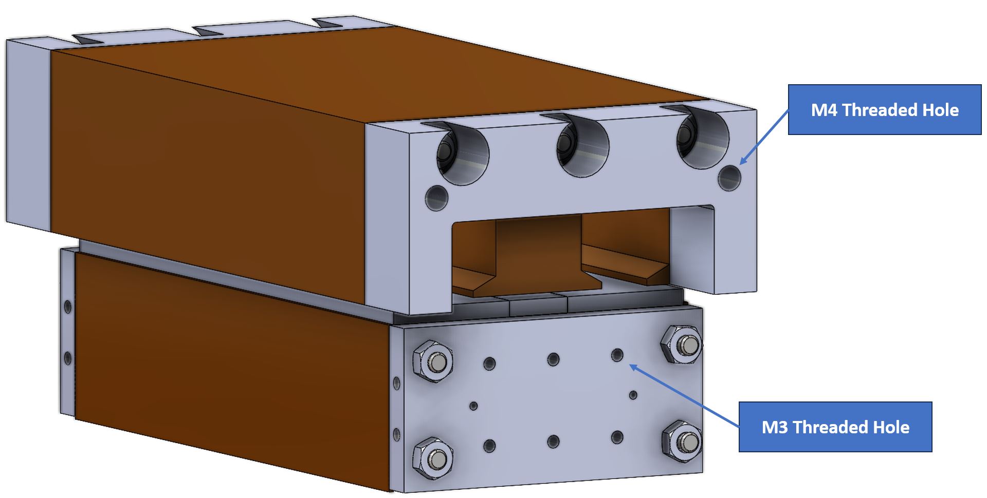
Let’s address the first question first. After the discussing with the designer of the machine, it appeared there are several M3 and M4 threaded holes on the exterior of the machine which could be used for mounting. However, they are located on the side of the machine, meaning some sort of small L-bracket could come in handy when securing the mover and stator.
2.
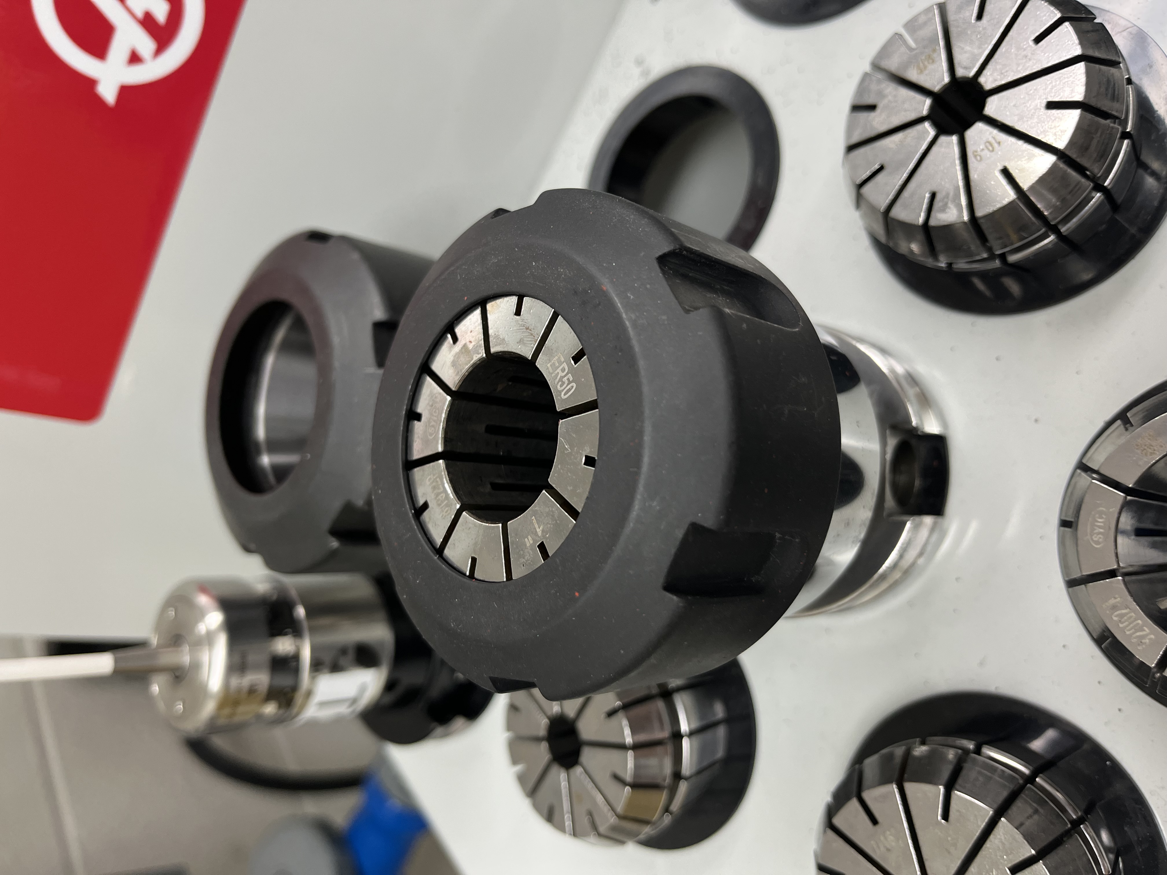
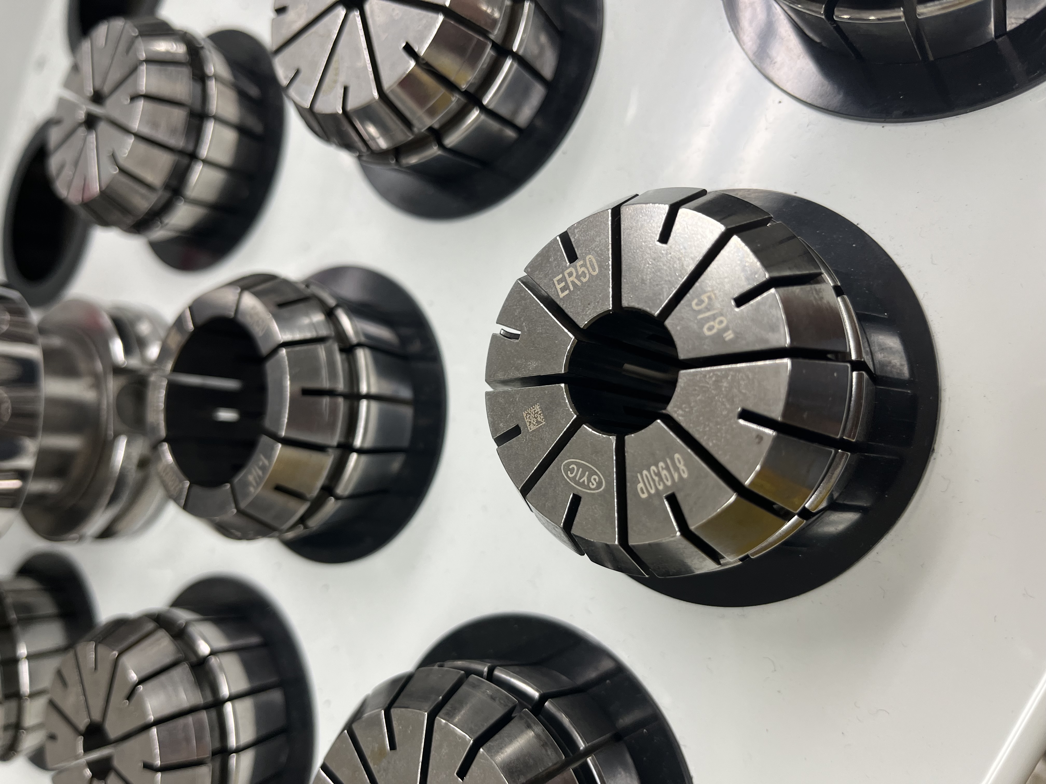
Next up, to attach the mover to the spindle, we opted for using the existing tool holders and collets we have in lab and design an attachment with a shaft feature. The CNC mill in lab is a HAAS TM-1, which uses a CAT40 taper, and the tool holders we use accept ER50 collets. After doing so digging, we were able to find a 1.25” sized collet, which appers to be the biggest diameter collet we have.
Note: While there are no general information on the exact amount of axial force these collets could handle before slipping out, it was believed that larger shaft diameter creates a greater surface area of contact between the shaft and the collet, which results in higher friction and clamping force and prevent the shaft to slip or move within the collet. This was an engineering decision we made, and was supported by the machining staff on campus for making such decision.
3.
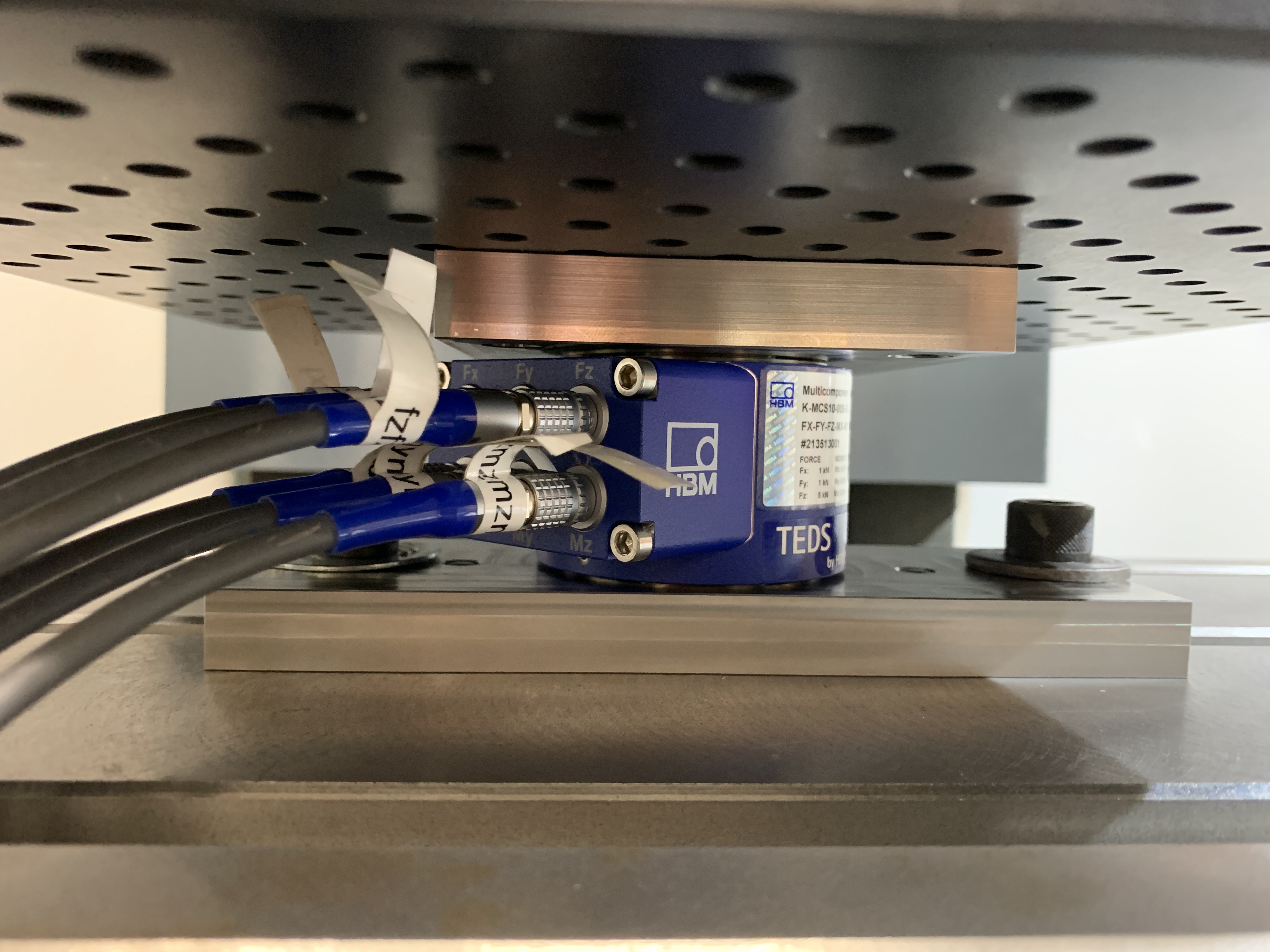
Let us take a look at the load cell we have in hand. The load cell is a HBM MCS10-005 multiaxis force sensor that has the capability of measuring the forces and moments simultaneously (3 moments & 3 forces). An image of the load cell and the dimensions are shown below.
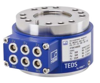
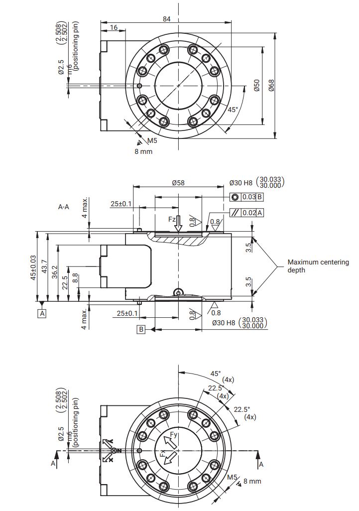
The load cell provides mounting features (12 M5 threaded holes) on each side. In terms of alignment, each side also has precision bore for centering and dowel pin for angular alignment. Based on these information, we likely could come up with some sort mounting plates around these dimensions, one for connecting the load cell to the mill table, and another one connecting load cell to the linear machine.
4.
Figuring out ways to lock the spindle position during testing is something we spent decent amount effort investigating. The TM-1 mill does not come with a built-in brake, meaning, there isn’t a way to mechanically stop/lock the spindle. However, the mill does come with an “Orient Spindle” option, which is an M-code (M19 to be specific) command that can rotate and fix the position of the spindle. This feature however, is not perfect. The way the spindle is able to “lock” itself to a set angular position is by using closed-loop feedback control, meaning the spindle is continously adjusting its own position according to feedback received from the spindle encoder. When an external torque is applied to the spindle, the spindle motor must react to the torque by providing a counter torque. This could potentially overload the spindle motor if the applied external torque is too high.
Fortunately, the load generated by the linear machine is a distrubited load along the long edge, meaning if the linear machine is carefully placed at the center, the potential unwanted torque generated could be minimized. For this reason, the team decided to move forward with using the orient spindle feature to fix the spindle position. To mitigate the risk of overloading the spindle, the team would also closely monitor the spindle load and terminate the current to the linear machine immediately if the load on the spindle is deemed to high.
NOTE: See the documentation on HAAS website regarding the M19 Orient Spindle feature.
5.
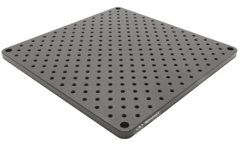
To keep the design simple, an optical breadboard could come in handy to mount the linear machine. These optical breadboard were previously used as the baseplate of another project. They are nice and conveient as they come with different sizes and has a grid of threaded mounting hole on them. Not only that, this also means the user can easily swap out machines and put on one with different size, making it universal.
3. Design
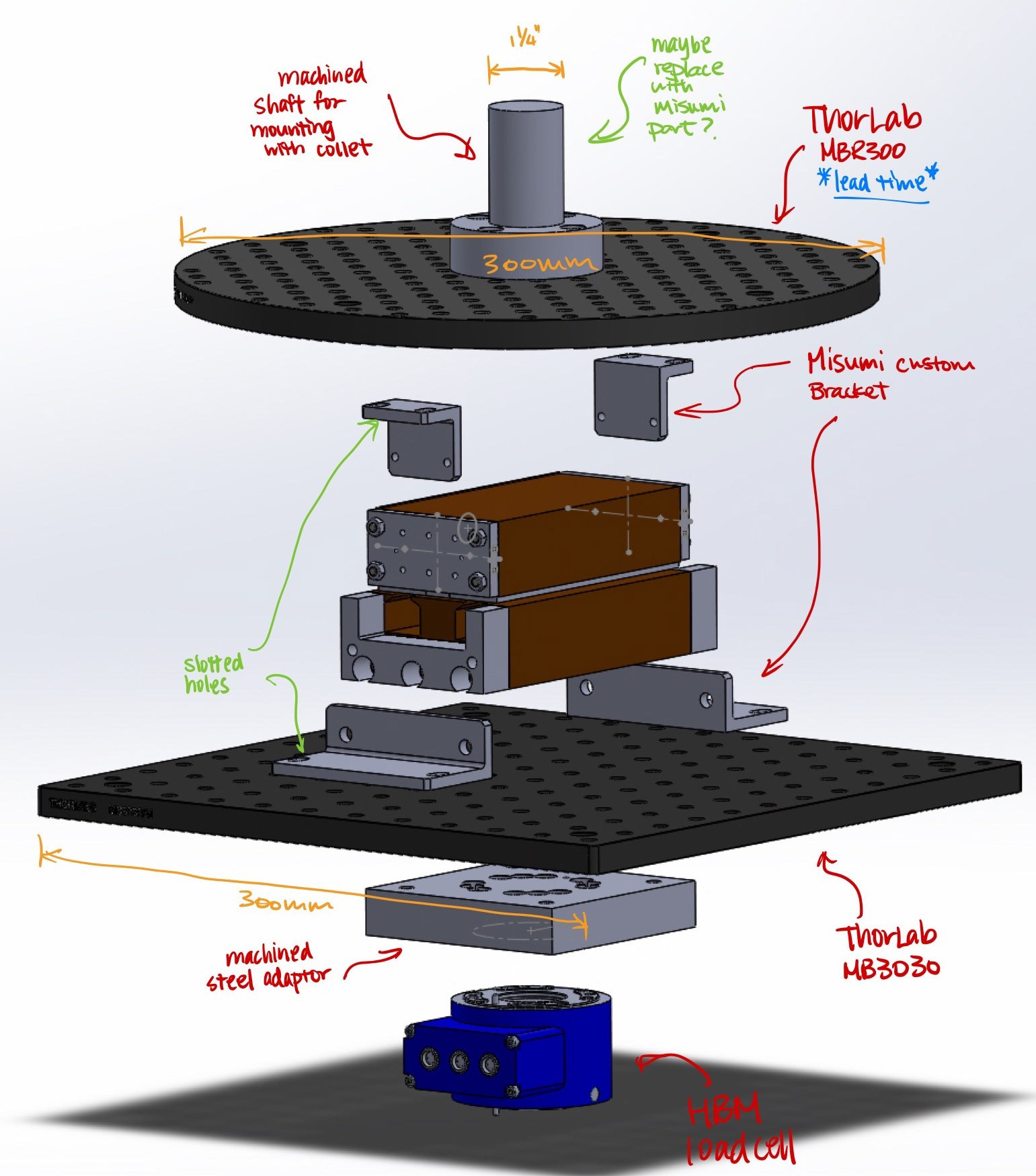
As discussed in the brainstorming section, connecting the mover to the spindle requires an attachment featuring a shaft to couple with the collet. To address this, we designed an attachment with an 1.25” OD, which can be conveniently fastened to the upper optical breadboard. Subsequently, the mover can be affixed with using custom L-brackets available from MISUMI. A design sketch of the of the overall assembly was created in SolidWorks and shown below.
Similarly, the stator is attached to the lower optical breadboard in a similar fashion. Between the lower optical breadboard and the load cell is the adapator plate to connect both pieces together. The bottom side of the load cell is then connected to another adapator plate (not shown in the figure below) that would be bolted down to the mill table.
Below, you’ll find animations illustrating both the assembly process of the test fixture and the method by which it will be securely bolted to the mill table.
Below is the engineering draw for the 1.25” OD attachement for connecting the mover assembly to the spindle.
And here is another drawing for the adaptor plate between the load cell and lower optical breadboard.
Adapter plate for mounting the load cell to the mill table.
Note: Dowel holes with tight tolerances were added onto these parts. They were intended for alignments between components and to assist eliminating measurement error.
4. Assembly
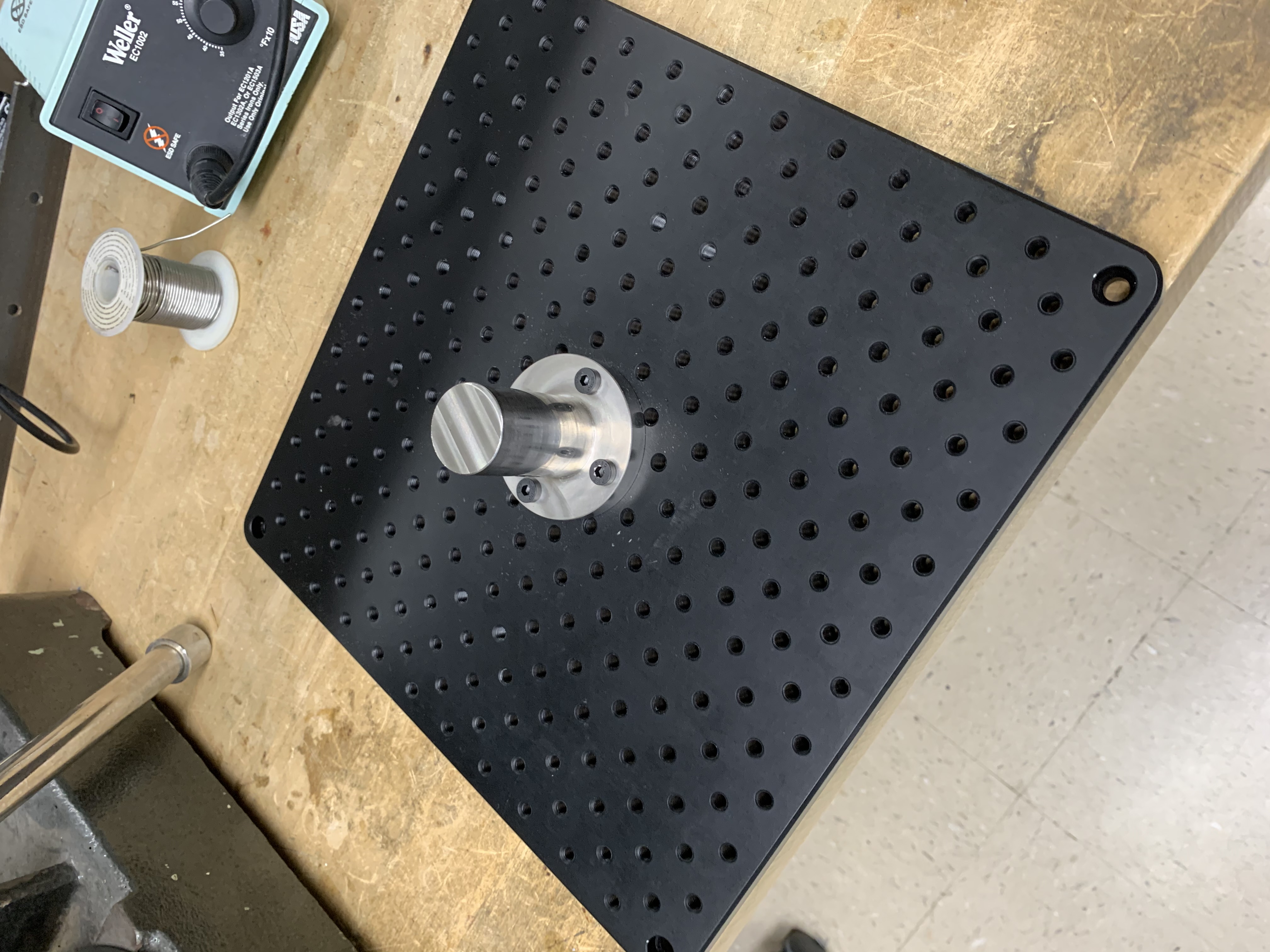
The attachment for connecting the upper breadboard to the mill spindle was machined out of 304 stainless steel. Figure below shows the attachement directly mounted to the breadboard with four M6 fasteners.
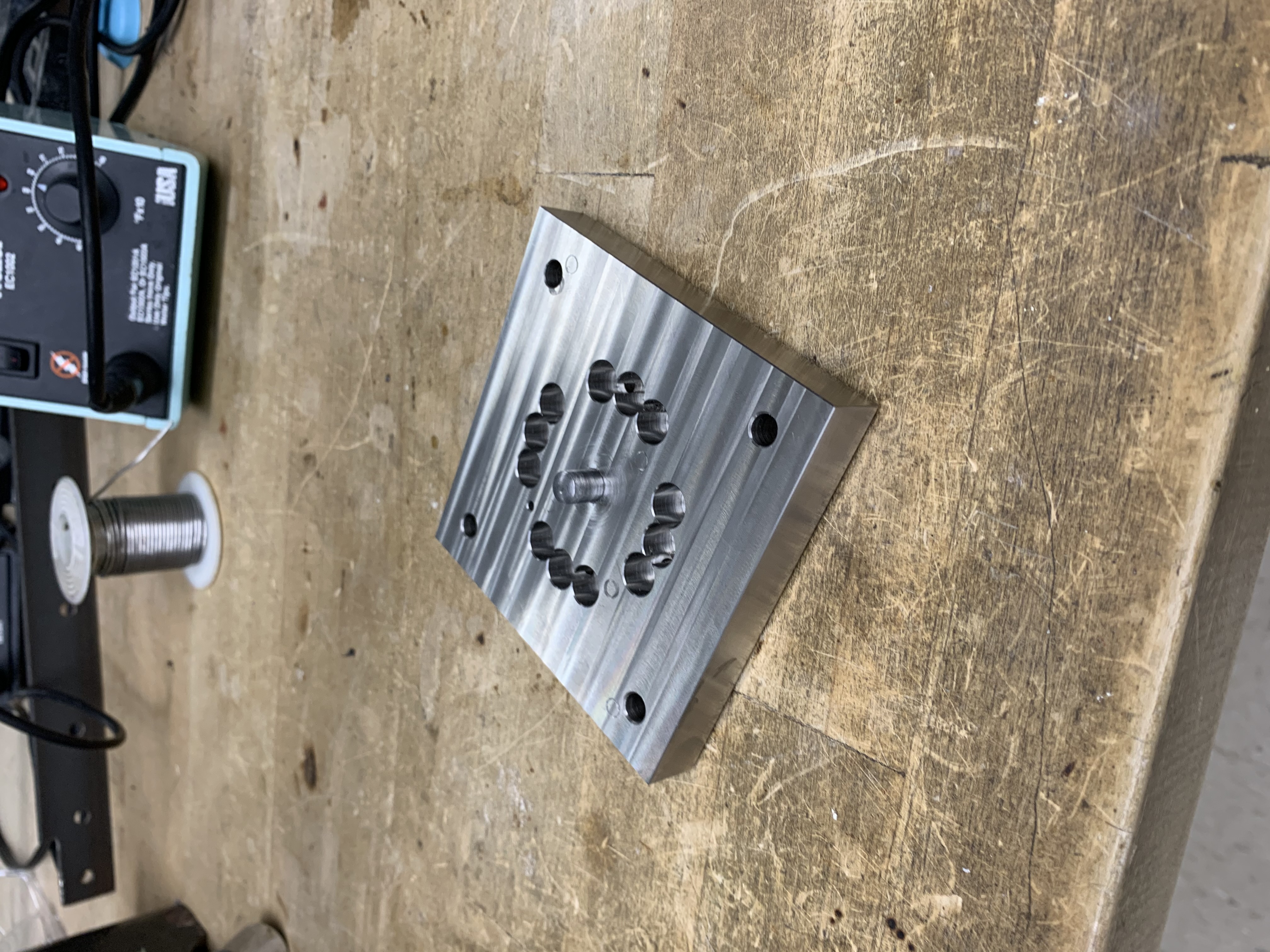
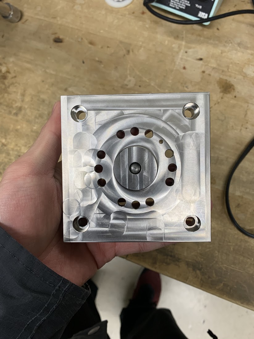
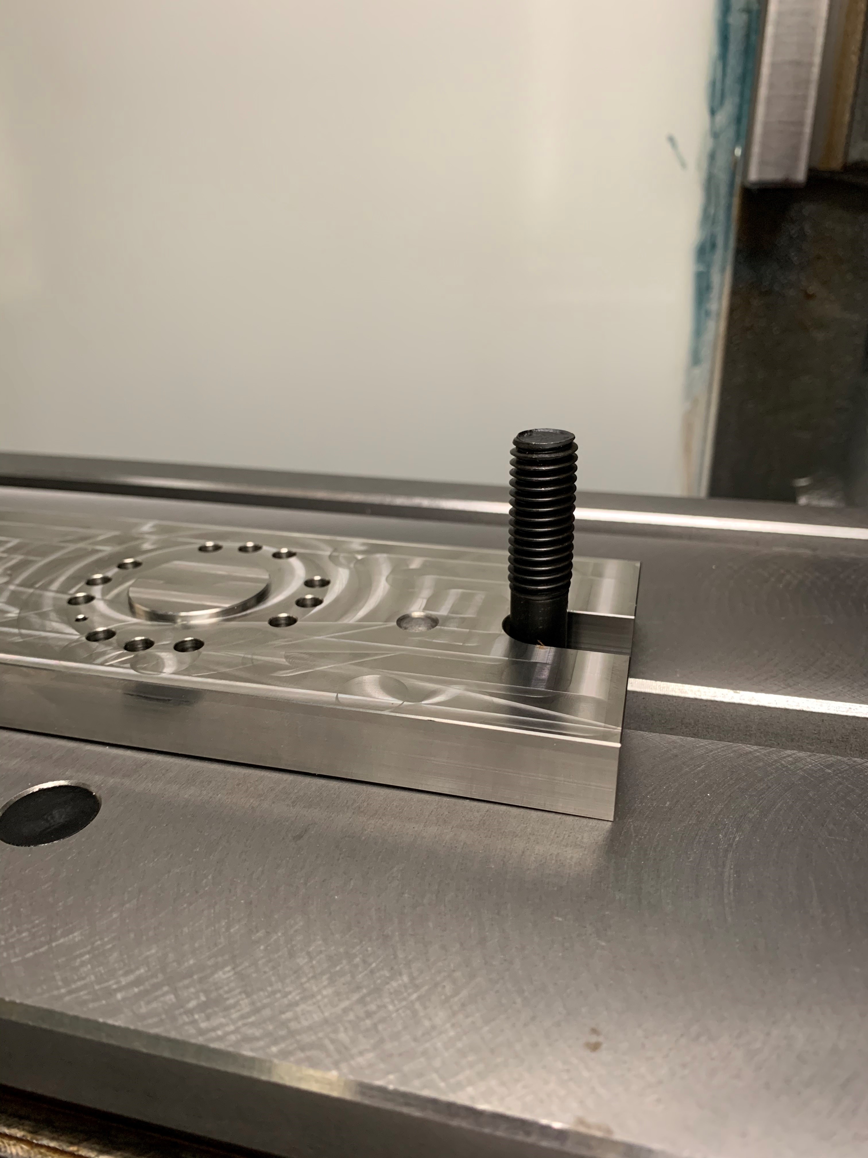
The adaptor plate for mounting the lower breadboard to the load cell was also similarly machined out of 304 stainless steel. To align the center of the breadboard, a dowel pin was pressed fit into the central machined hole. The breadboard was modified to have a drilled and reamed hole in the center to align the two parts together. Figures of the finished machined adapater plate are shown below.
4.1 Slight issue …
For unknown reasons, the adapter plate for connecting the load cell to the mill table came to us slightly bent/uneven at the bottom surface (see figures below) … we communicated with the machine shop that machined the parts for us and we suspected there was issue with fixturing when machining. The machine shop was kind enough to remachine a new part for us, but a pretty odd incident needless to say…
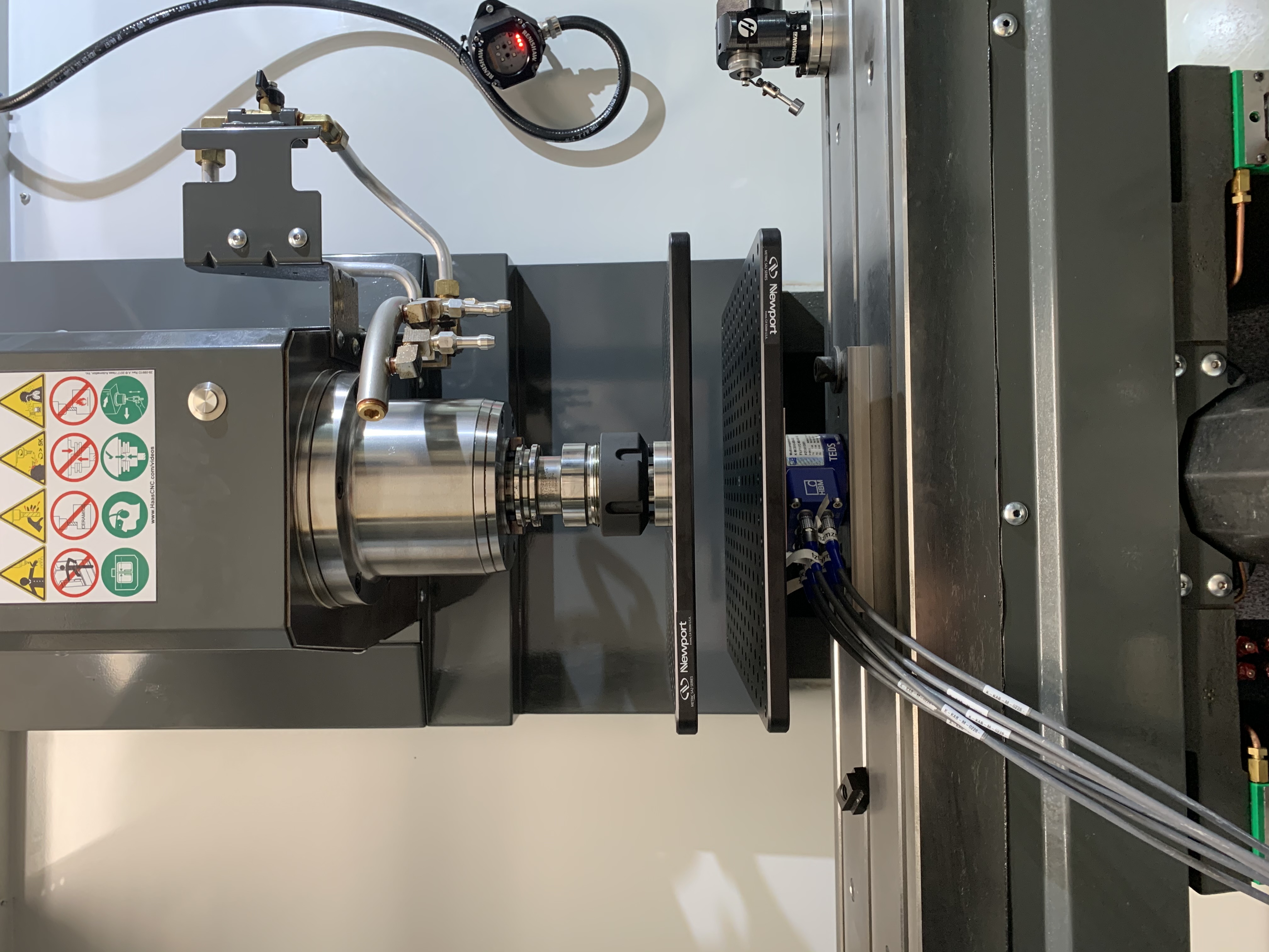
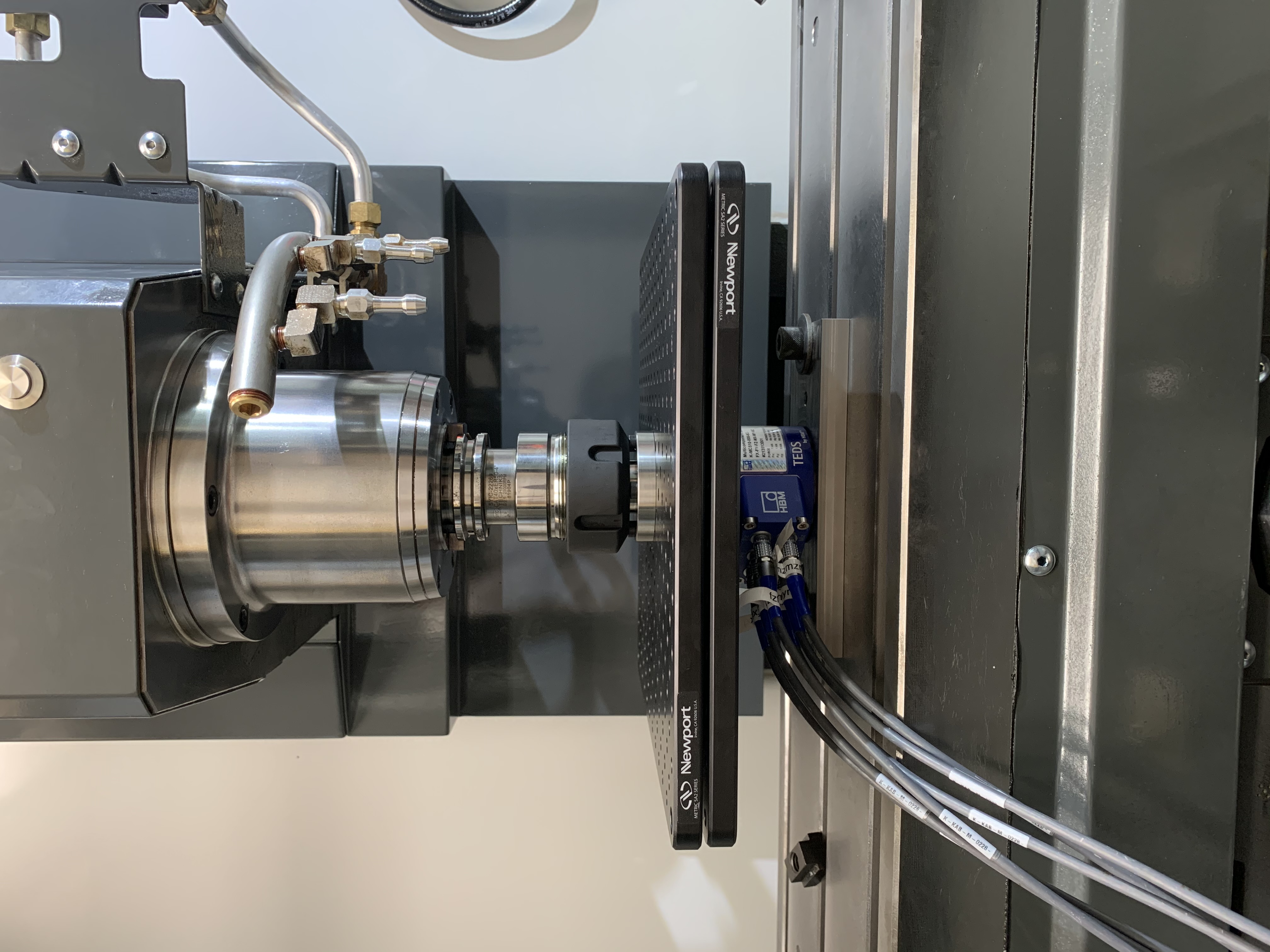
With the new part came in the mail, we proceeded with mounting all the componets to the mill. Figure below shows the linear machine texture setup mounted onto the mill.
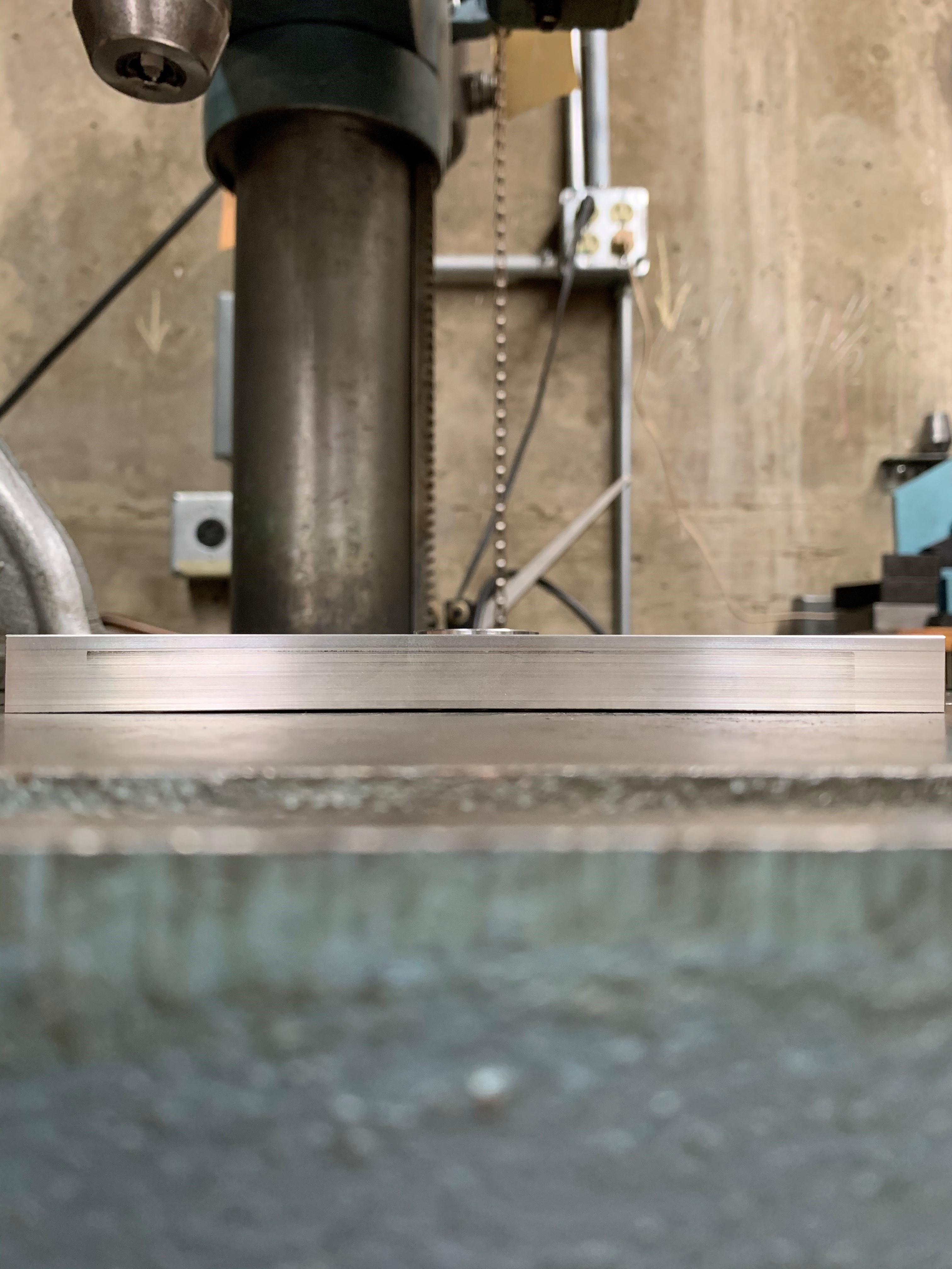
Side view of the test fixture is shown below. One thing in particular we had to ensure was aligning the two plates as parallel as possible. We were able to achieve this by making incremental adjustment to the angular with the help of precision dial indicator.
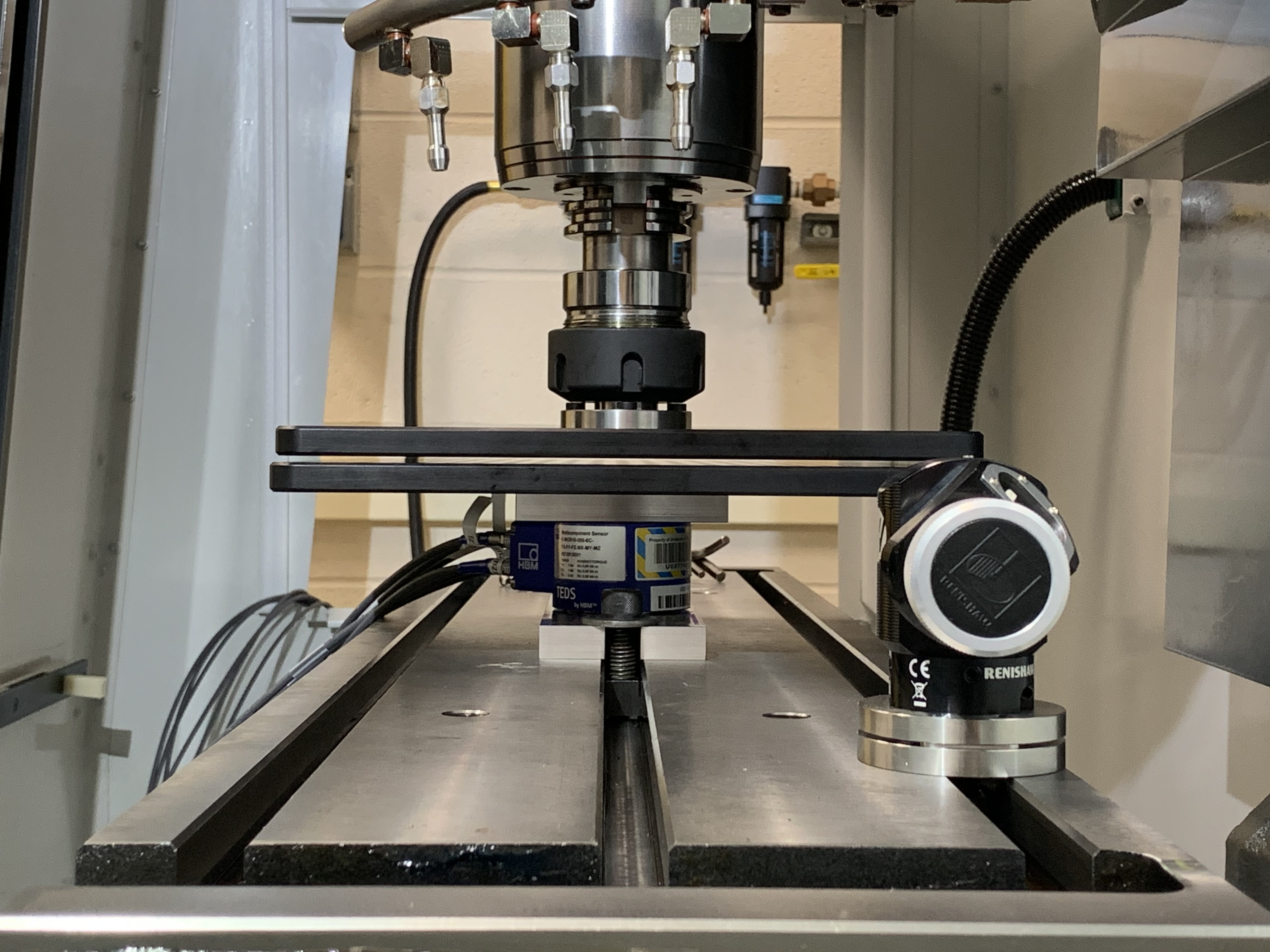
A shot of the load cell mounted and secured with the adaptor plates.
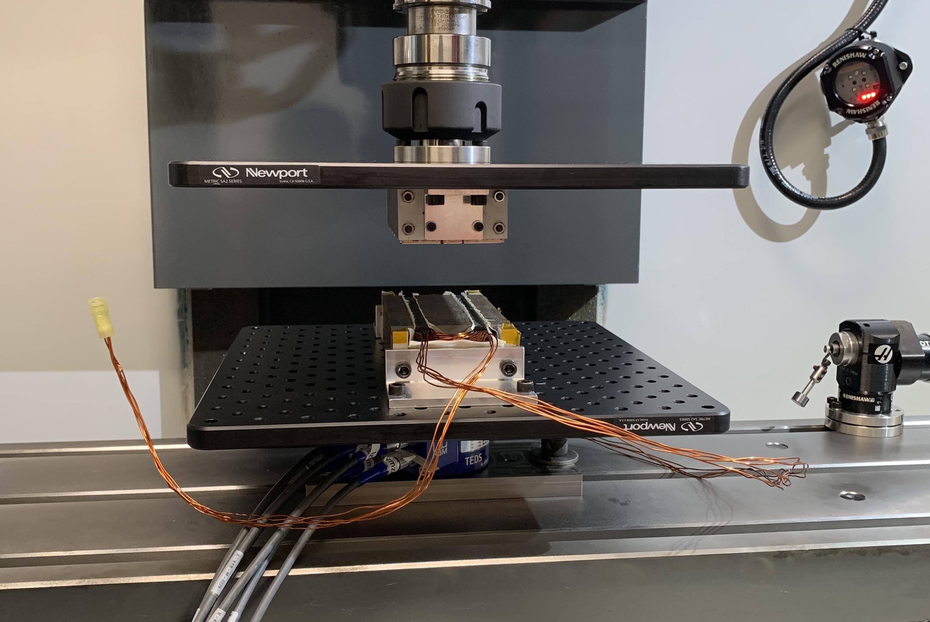
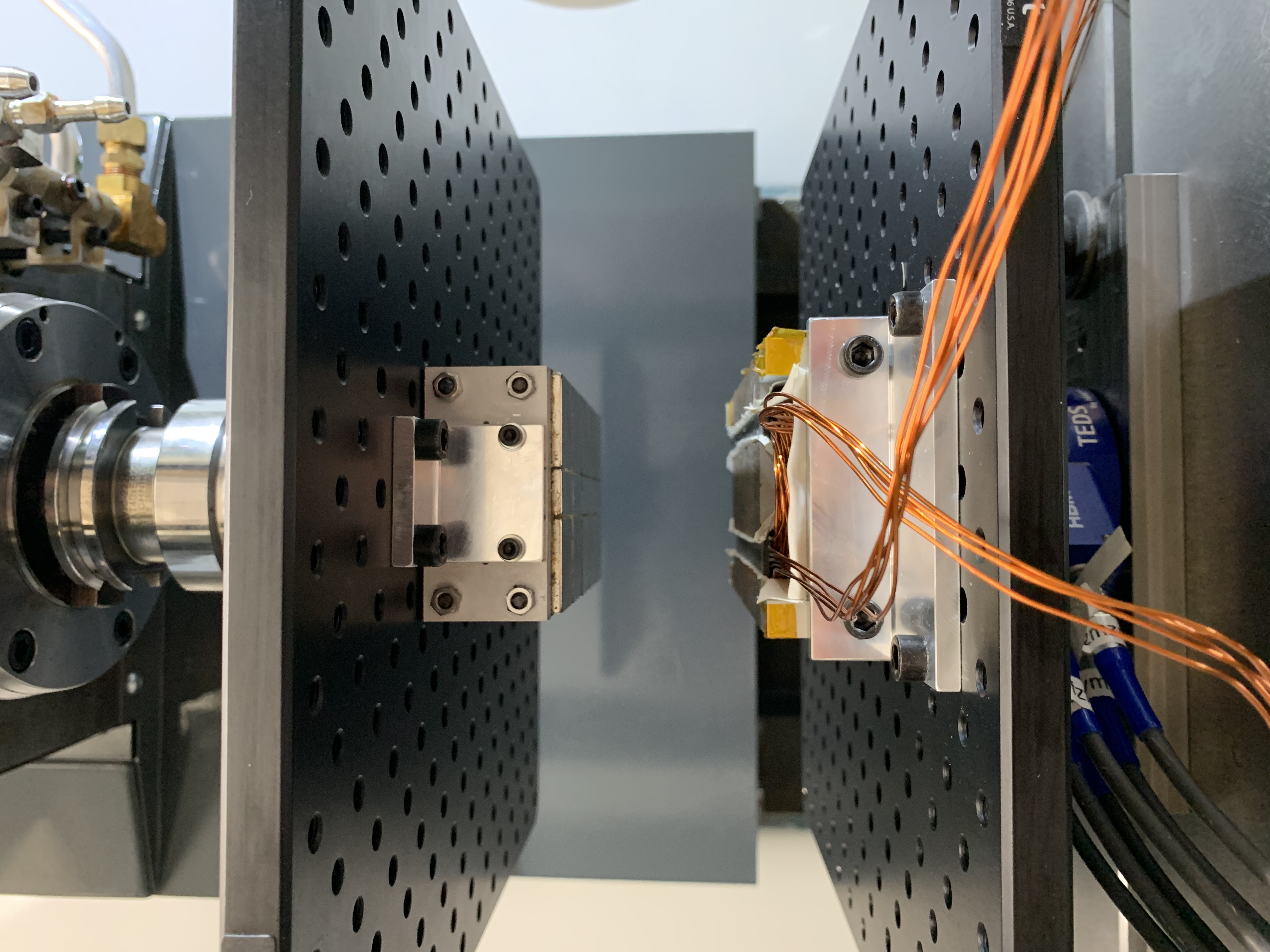
View of the prototype linear machine full mounted!

5. Future Improvements
As mentioned in the brainstorming section, one of the issues we expected to encounter was the inability to fully lock the spindle in place during testing. When an external torque was applied to the spindle, the closed-loop feedback control would attempt to correct its angular position back to the commanded position. The video clip below shows that the angular stiffness did not meet the desired level our team had aimed for. A new/different mounting method would likely be necessary to improve the angular stiffness of this setup.