0. Overview
A dynamometer is an essential device used for characterizing electric machines to understand their performances. This particular dynamometer setup is designed for the WEMPEC research lab at UW-Madison, with the primary objective of conducting comprehensive tests on small-scale electric machines for research purposes. The dynamometer prototype possesses the capability to characterize machines rated at up to 10N-m of torque and a rotational speed of 3000RPM.
1. Background
When I first joined WEMPEC as an undergraduate researcher under the now ex-lab manager, Kyle Hanson, I was put in charge of prototyping a new desktop-size dynamomter. The main objective behind this project was to meet the growing demand for a more convenient and interchangeable dynamometer, which could streamline the testing process and eliminate the complexities associated with aligning a large-scale dynamometer in lab.
2. What is a “Dynamometer”…?
For those unfamiliar with the term dynamometer, you probably wondering, “What the heck is it?” In essence, a dynamometer is a device that can measure the rotational speed and torque output of an engine or electric motor, thereby enabling the precise determination of its instantaneous power and efficiency. A typical dynamometer consist of a load device (often time another electric motor) that can subject the system under test to controlled load and measuring the resulting output. A simple schematic of a dynamometer is shown below.

NOTE: For those who are interested in learning more in details about the inner workings of dynamometer, I would recommend checking out the dynamometer Wikipedia page here.
3. Design Requirments
Here are some of the few basic requirements for this dynamometer,
- Must fit on a typical lab bench. (about X by X).
- Able to couple to an IEC100 frame size machine.
- Able to fit the pre-selected Rockwell Kinetix MP Servo (used as load).
- Should have a full protective enclosure for operation.
Some nice features to have would be,
- An HMI (Human Machine Interface) to control the load motor.
- A mechanism for quick installation and removal of test motor without compromising shaft alignment.
For designing this prototype we also aimed for using as many off-the-shelf components as possible to reduce cost and machining needs.
4. Brainstroming
4.1 Mounting
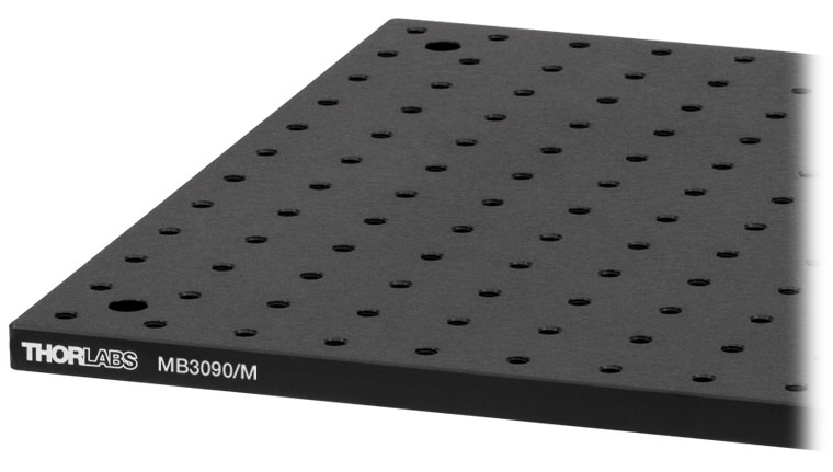
With the prototype’s size limit in mind, I searched for a suitable base plate for mounting all the components. The optical breadboard from ThorLabs caught my attention (see an example in figure below). One of the awesome things about these optical tables is the grid of threaded holes that you can mount things to.
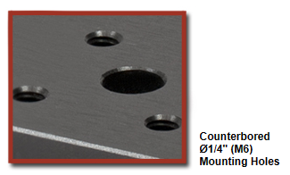
The pre-selected load servo motor is a Rockwell Kinetix MPL-A4540F-MJ74AA. The CAD model was obtained from the manufacture and shown below.
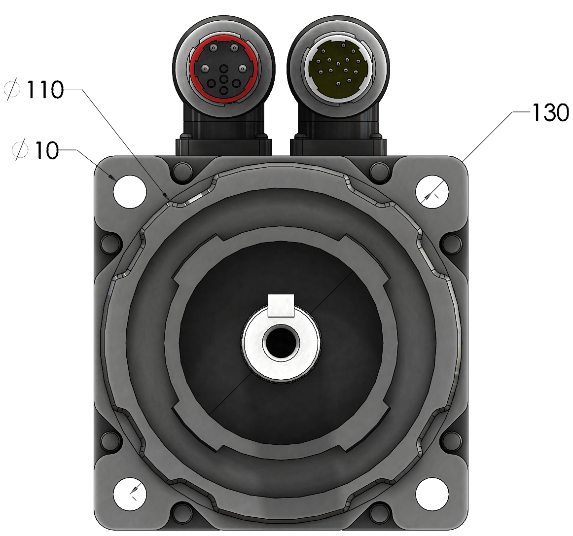
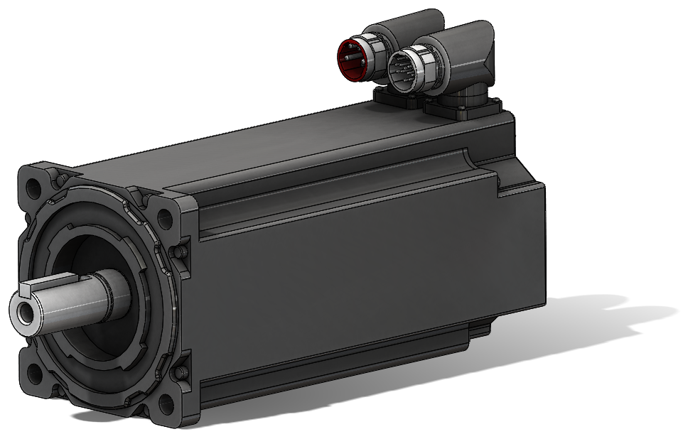
Based on the dimensions provided by the manufacturer, the servo has an IEC frame size of 100. For that, a fixture is needed to securely mount it.
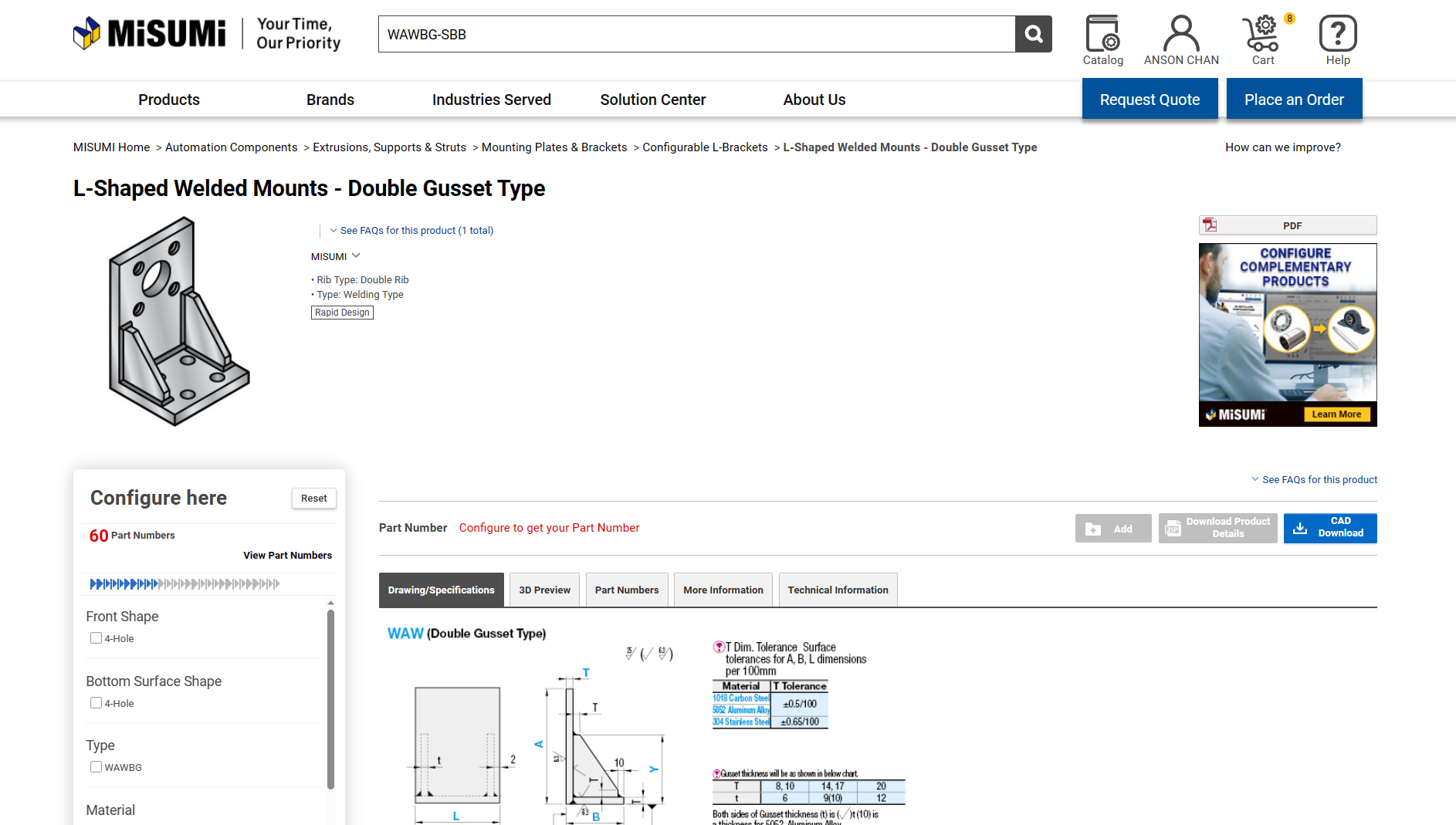
One of my favorite places to look for custom parts when working on a project is MISUMI, a Japanese company that provides extensive amount of fixed and configurable components for users. After doing some digging, I was able to find this L-Shaped Welded Mounts on their website, which I think could be a pretty good option for mounting to the optical breadboard.
4.2 Interchability / Alignment
For a dynamometer, shaft alignment is extremely cruical in obtaining accurate results for experiment. Not to mention, misalignment also means more mechanical wear, which directly compromise reliability of the machine.
While I was search of the optical breadboard, I came across these optical carriers and rails from OptoSigma. These optical carriers are advertised to have the ability to freely slide on the rails (see animation below) and can be locked in place, which seems to be a decent option for quickly installing/removing test motor from the dynamomter. However, in terms of alignment between the load servo motor, manual alignment is still required.
5. Design
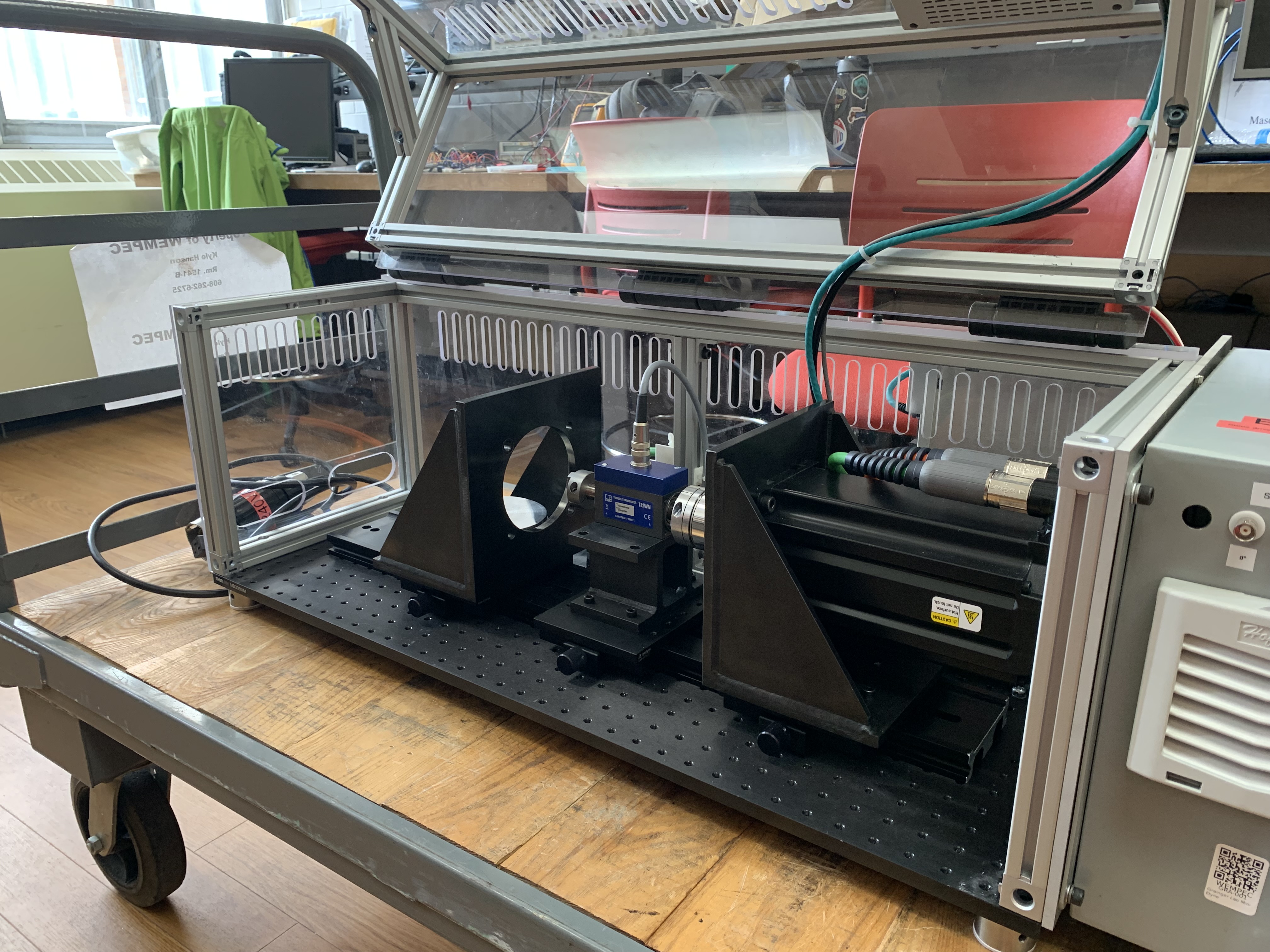
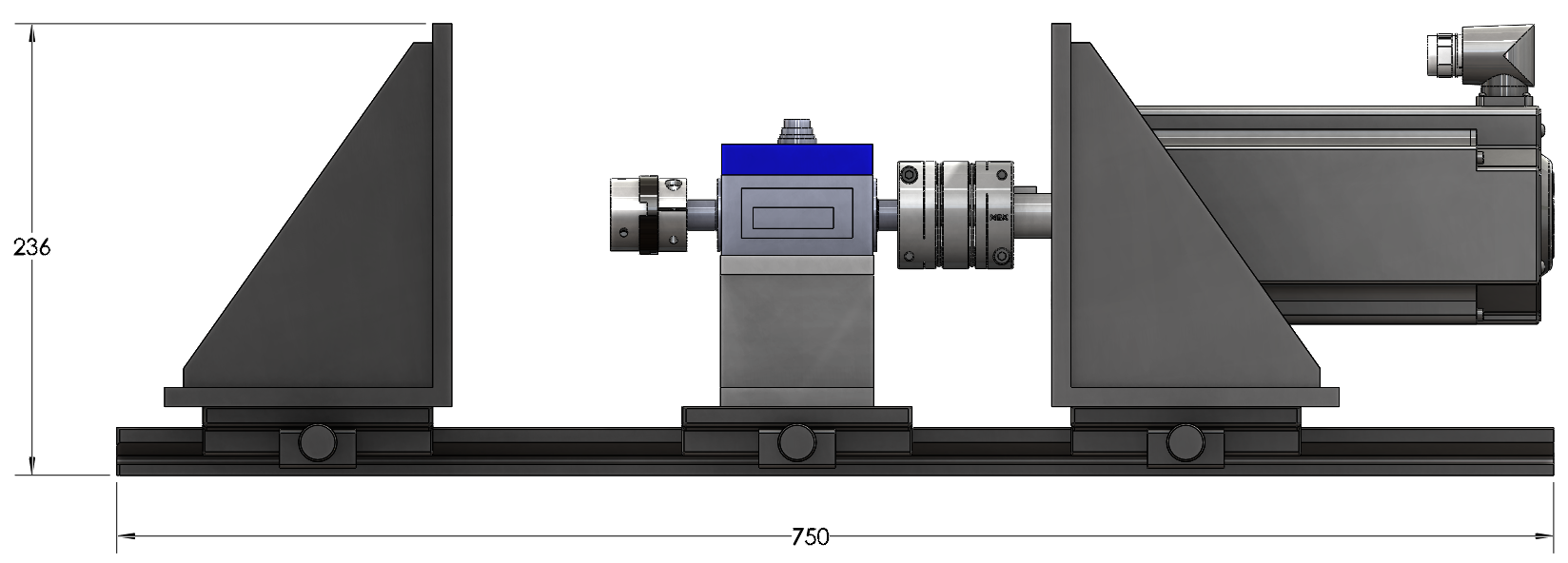
5.1 Dynamometer Setup
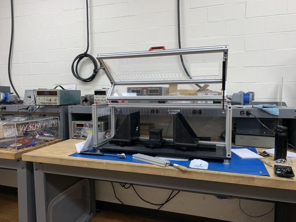
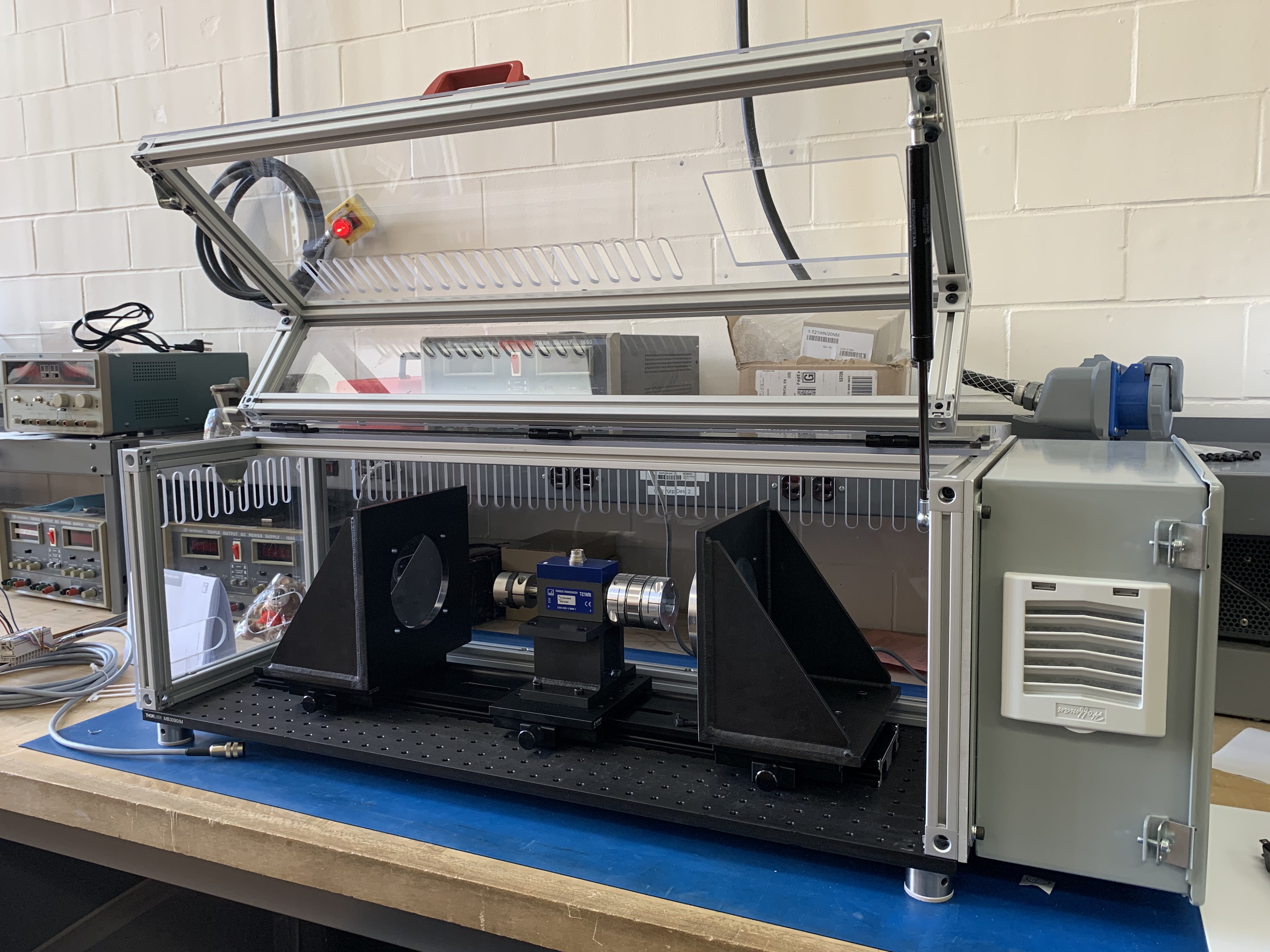
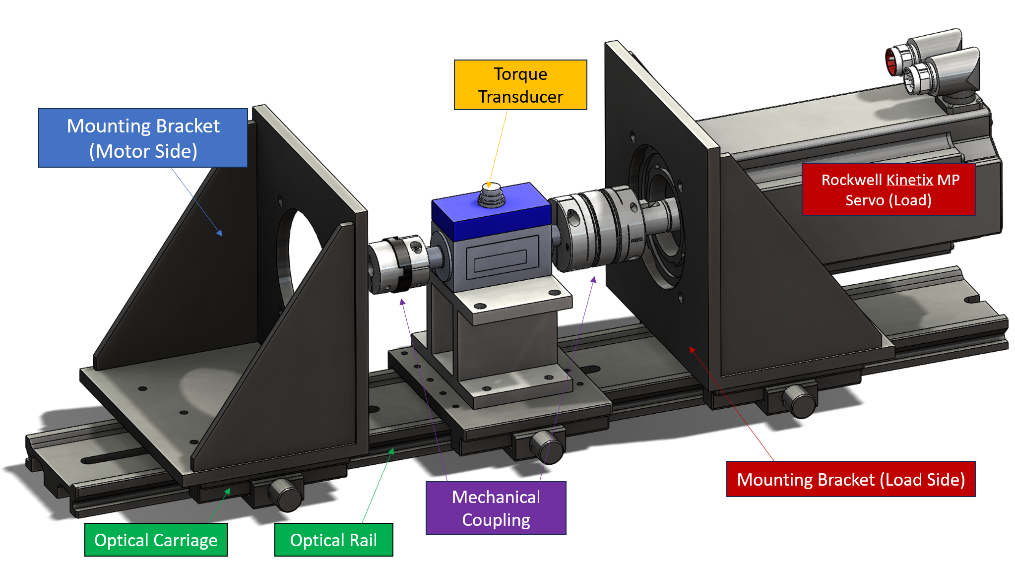
After spending some time in SolidWorks I came up with an initial design for the prototype. A view of the setup with annotations is shown below. The Rockwell Kinetix MP servo for providing load is mounted onto a configured MISUMI L-Shaped bracket and bolted down onto a optical carrier. The load servo is then similiar mounted and coupled to the torque transducer that is sitting on a configured steel pedestal. The servo and torque transducer techically operate as a single unit. However, for interchangability sake, I have made the decision of seperating them, which users could easily swap these components out.
The mounting bracket can also be easily removed for user to install/remove their test motor. When they need to couple back to the torque transducer, they just need to drop it on the optical rail, slide it, couple motor shaft to the coupling, tighten it and voila. Animation below shows the mounting and sliding action of the test motor using optical rail and carriage.
5.2 Enclosure
I opted for the ThorLab MB3090/M - Aluminum Breadboard as the bedplate for the dynamometer setup. ThorLab also offered other bedplate options with vibration damping features. But for this prototype, I opted for the cheaper option to reduce cost. If we feel the dampening feature is needed, we can always swap it out later on.
As for the enclosure frame, the good old T-slot 8020 comes in handy. And obviously, it would not be an enclosure without some polycarbonates as protective panels! I chose the panels to be 1/4” thick as that is the only thickness we have in stock in the lab storage, and if I need to cut them to shape all I need is bringing the .dxf files to the machine shop on campus and they will waterjet them for us.
5.3 Electrical Components
Selecting the right electrical components needed for this prototype was somewhat challenging for me. Despite knowing what the servo’s specification was, picking out parts to pair up the servo with was difficult as there were countless of options to choose from.
Lucky enough, Kyle was kind enough to pair me up with Lee, another research assistant in the lab who was able to guide me through the electrical component selections.
5.3.1 Servo Drive
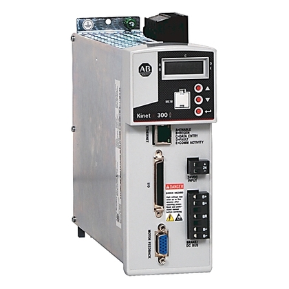
The pre-selected servo is an Allen-Bradley MPL-A4540F-MJ74AA with rated speed of 3000RPM and rated power output of 2.6kW. Consequently, a drive capable of accommodating 2.6kW or higher is necessary. After a thorough catalog review, we’ve selected the Allen-Bradley Kinetix 300 2097-V33PR6. This drive offers a rated continuous power output of 3kW and the flexibility to operate on either 120V 1φ or 240V 3φ at higher speed.
5.3.2 HMI & PLC
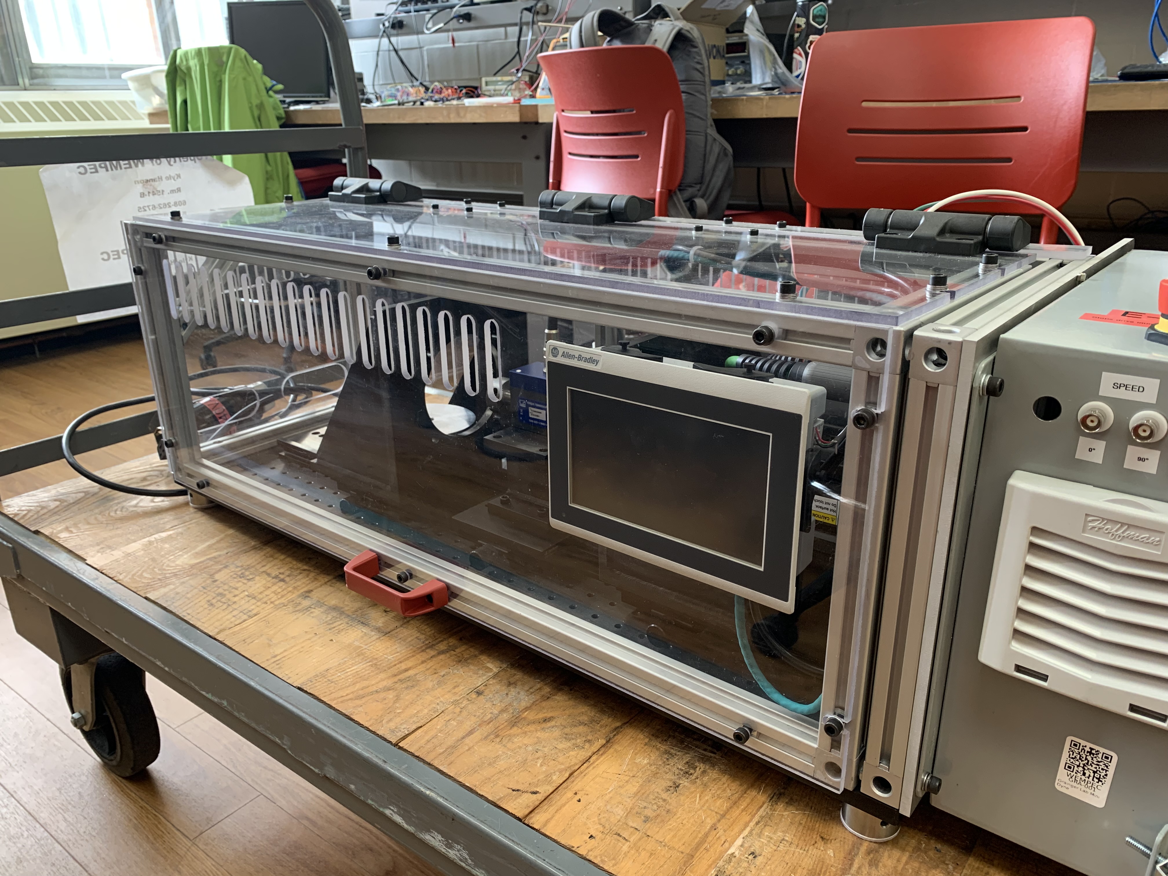
As mentioned earlier one of the nice features we would like the dynamometer prototype to have is an HMI (Human Machine Interface) to operate the servo motor. The HMI we selected is the 7” PanelView 800 offered by Rockwell Automation (in case you are wondering … it is the parent company of Allen-Bradley). This HMI panel comes with a TFT Touchscreen and the customizability of creating your own interface for you specific application, which in my opinion is pretty sweet.

In addition, in order to make this HMI work with the drive we will need a PLC (Programmable Logic Controller). We paired it up with a Micro820™ controller (also by Rockwell). This is one of basic controller that offers RJ45 Ethernet coomunication, whcich is also the standard for the HMI and drive.
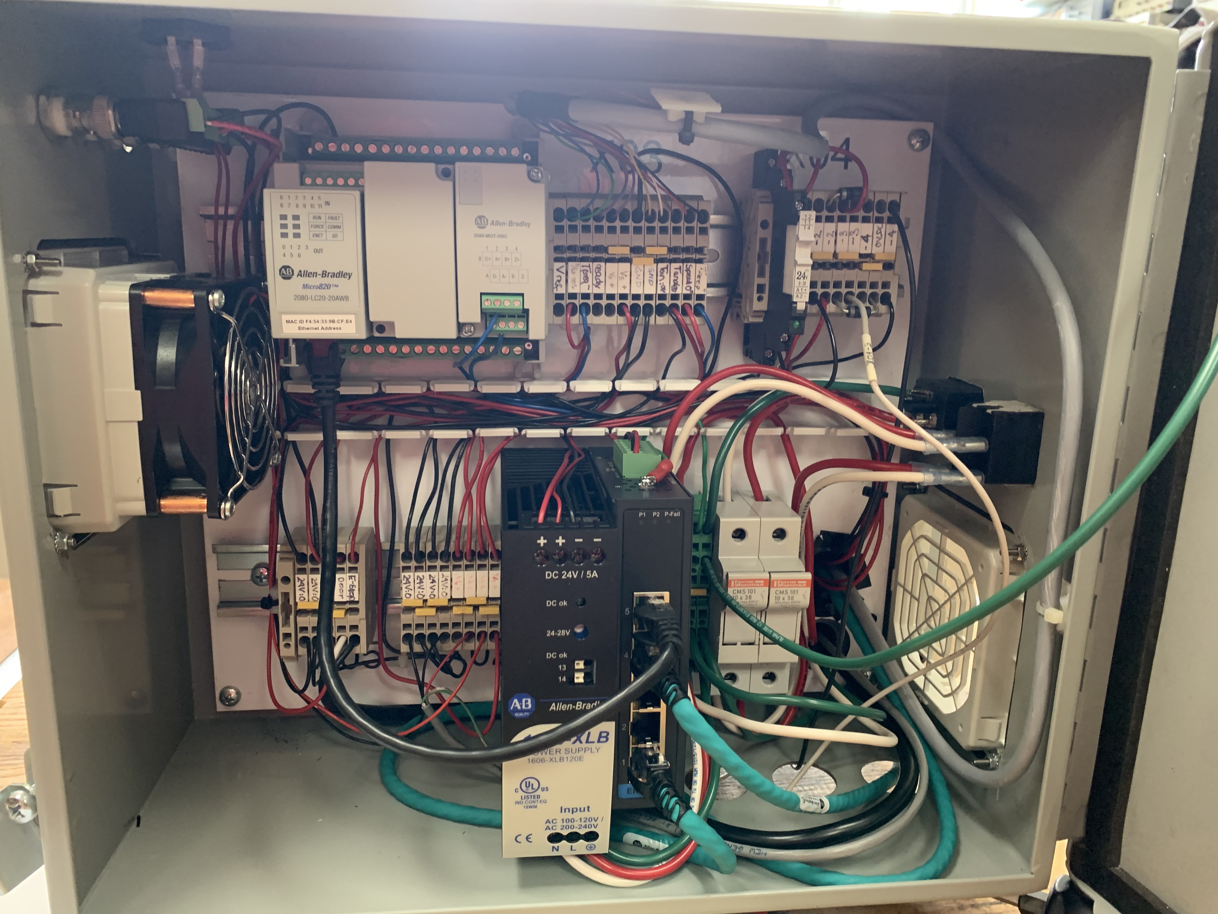
5.3.3 Relay, Ethernet Hub, Fuse, etc …
Some other components such as the relay for controlling the servo brake and and ethernet hub for hooking up all the commiunication deviced would be needed. Being in a large research lab also means we have plenty of these extra componenets laying around, so we planned on just digging through the storage room when we need those parts.
5.3 Mounting
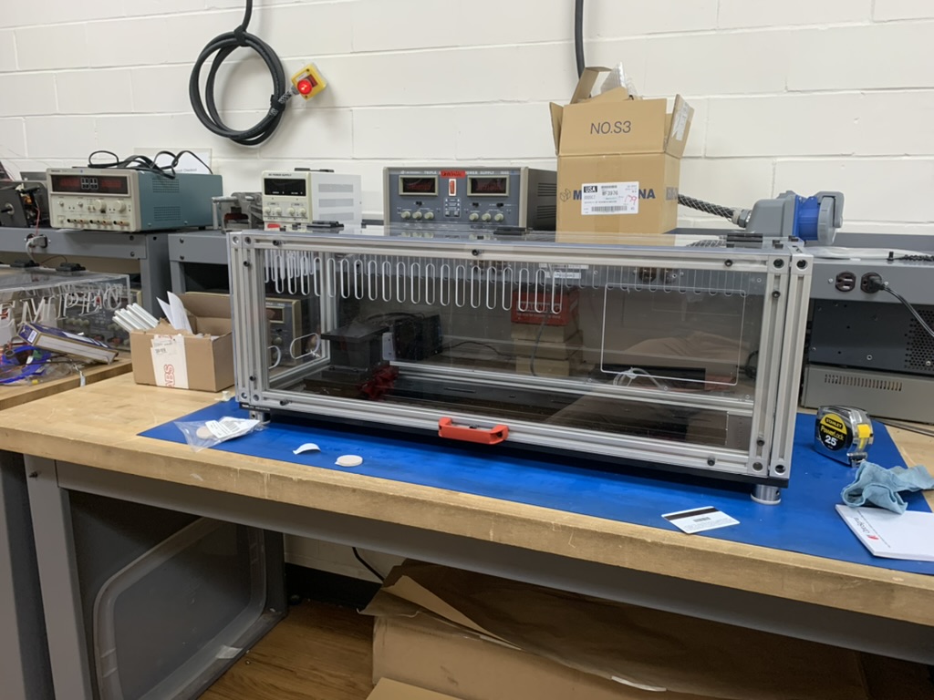
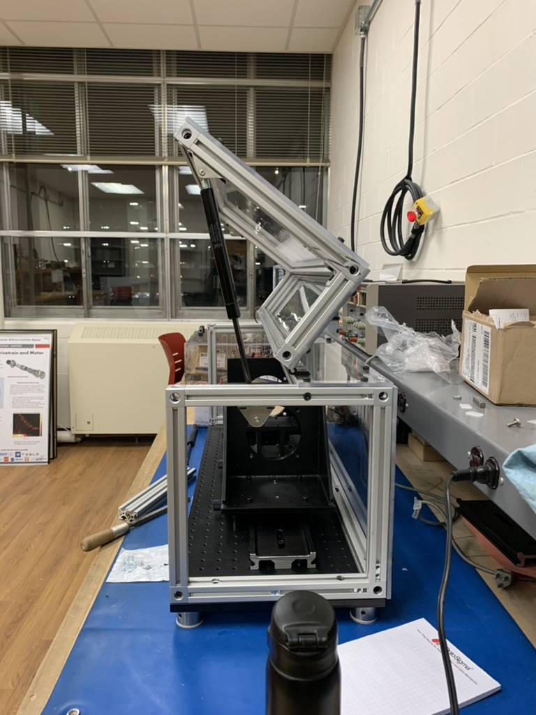
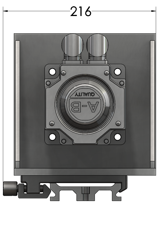
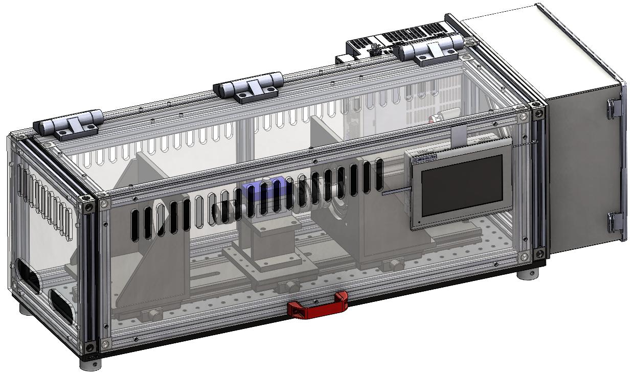
Animation below shows the overall assembly of the prototype with the 8020 enclosure. The enclosure was designed to have heat ventilation cutout on the polycarbonate panels, and soft-close friction lid hinges for the enclosure door.
In terms of mounting the electrical components, we decided on mounting the HMI panel on the enclosure door. All the electrical components (apart from the drive) would be housed within the electrical enclosure (mounting on the right side of the setup.) And for the drive, would be mounted directly behind the enclosure.
6. Assembly